MAX66140
full details including graphics of the data coding
schemes and SOF/EOF timing, refer to ISO 15693-2,
Sections 7.2, 7.3, and 8.
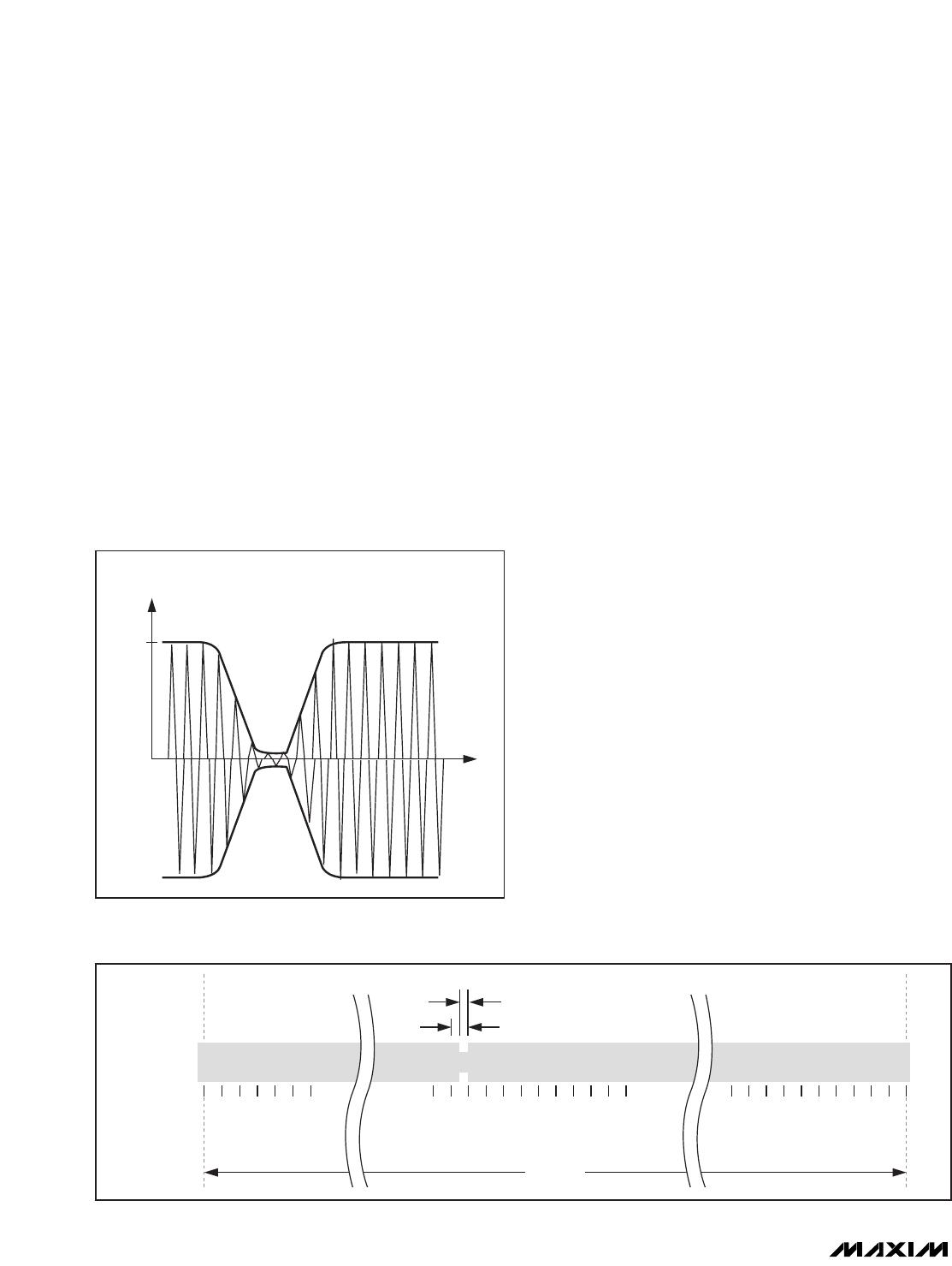
The path from master to slave uses amplitude modula-
tion (Figure 6); the modulation index can be either in
the range of 10% to 30% or 100% (ISO 15693-2,
Section 7.1). The standard defines two pulse-position
coding schemes that must be supported by a compli-
ant device. Scheme A uses the “1 out of 256” method
(Figure 7), where the transmission of 1 byte takes
4.833ms, equivalent to a data rate of 1655 bits/s. The
location of a modulation notch during the 4.833ms con-
veys the value of the byte. Scheme B uses the “1 out
of 4” method (Figure 8), where the transmission of 2
bits takes 75.52µs, equivalent to a data rate of 26,484
bits/s. The location of a modulation notch during the
75.52µs conveys the value of the 2 bits. A byte is trans-
mitted as a concatenation of four 2-bit transmissions,
with the least significant 2 bits of the byte being trans-
mitted first. The transmission of the SOF pattern takes
the same time as transmitting 2 bits in Scheme B. The
SOF pattern has two modulation notches, making it dis-
tinct from any 2-bit pattern. The position of the second
notch tells whether the frame uses the “1 out of 256” or
“1 out of 4” coding scheme (Figures 9 and 10, respec-
tively). The transmission of the EOF pattern takes
37.76µs; the EOF is the same for both coding schemes
and has one modulation notch (Figure 11).
The path from slave to master uses one or two subcar-
riers, as specified by the Subcarrier_flag bit in the
request data packet. The standard defines two data
rates for the response, low (approximately 6,600 bits/s)
and high (approximately 26,500 bits/s). The
Data_rate_flag bit in the request data packet specifies
the response data rate. The data rate varies slightly
depending on the use of one or two subcarriers. The
LSb is transmitted first. A compliant device must sup-
port both subcarrier modes and data rates.
In the single subcarrier case, the subcarrier frequency
is 423.75kHz. One bit is transmitted in 37.76µs (high
data rate) or 151µs (low data rate). The modulation is
the on/off key. For a logic 0, the subcarrier is on during
the first half of the bit transmission time and off for the
second half. For a logic 1, the subcarrier is off during
the first half of the bit transmission time and on for the
second half. See Figure 12 for more details.
In the two subcarrier cases, the subcarrier frequencies
are 423.75kHz and 484.28kHz. The bit duration is the
same as in the single subcarrier case. The modulation
is equivalent to binary FM. For a logic 0, the lower sub-
carrier is on during the first half of the bit transmission
time, switching to the higher subcarrier for the second
half. For a logic 1, the higher subcarrier is on during the
ISO 15693-Compliant Secure Memory
8 _______________________________________________________________________________________
ABRIDGED DATA SHEET
Figure 6. Downlink Modulation (e.g., Approximately 100%
Amplitude Modulation)
....... ........2
.....