7
LTC1479
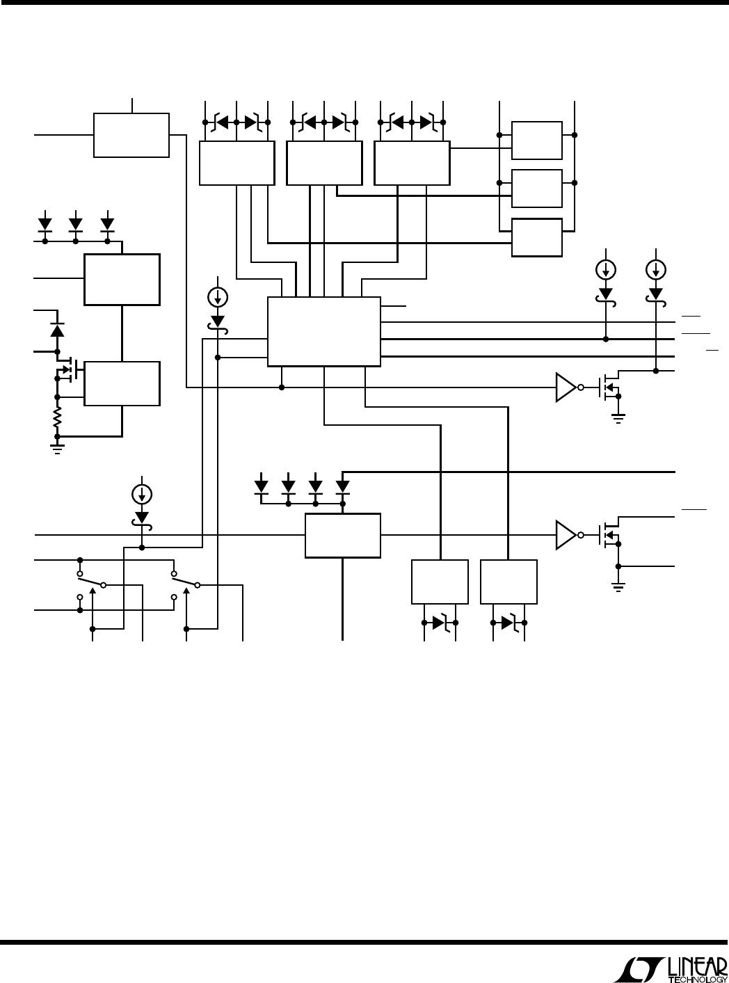
PIN FUNCTIONS
UUU
SENSE
–
(Pin 14):
Inrush Current Input. This pin should
be connected directly to the “bottom” (output side) of the
low valued resistor in series with the three input power
selector switch pairs, SW A/B, SW C/D and SW E/F, for
detecting and controlling the inrush current into and out
of the power supply sources and the output capacitor.
Battery Charging Switches
GG, GH (Pins 29, 27): Charger Switch Gate Drive. These
two pins drive the gates of the back-to-back N-channel
switch pairs, SW G and SW H, between the charger output
and the two batteries.
SG, SH (Pin 28, 26): Source Returns. These two pins are
connected to the sources of SW G and SW H respectively.
A small pull-down current source returns these nodes to
0V when the switches are turned off.
CHGMON (Pin 31):
Battery Selector Output. This pin is
the output of an internal switch which is connected to
BAT1 and BAT2 and connects the positive terminal of the
selected battery to the voltage feedback resistors in the
charger circuit.
Microprocessor Interface
DCINGOOD (Pin 25): Comparator Output. This open-drain
output has an internal 2µA pull-up current source con-
nected through a diode to the V
CCP
power supply. An
external pull-up resistor can be added if more pull-up
current is required. This output is active high when the DC
supply rises above the programmed voltage.
LOBAT (Pin 3): Comparator Output. This open-drain out-
put does not have an internal pull-up current source and
is active low when the selected battery voltage drops
below the programmed voltage.
DCIN/BAT (Pin 24): Selector Input. This high impedance
logic input allows the µP to make the ultimate decision on
the connection of the DC power source, based upon the
DCINGOOD pin information. In some minimized systems,
the DCIN/BAT pin may be connected directly to the
DCINGOOD pin.
BATDIS (Pin 23): Battery Disconnect Input. This high-
impedance logic input has a built-in 2µA pull-up current
source and allows the µP to disconnect the battery from
the system.
3DM (Pin 22): Three Diode Mode Input. This high imped-
ance logic input has no built-in pull-up current source.
Connect a 100k resistor from this pin to ground to ensure
three diode mode operation from a “cold start.”
CHGSEL (Pin 21): Battery Charger Selector Input. This
high impedance logic input has a built-in 2µA pull-up
current source and allows the µP to determine which
battery is being charged by connecting the selected
battery to the charger output via one of the switch pairs,
SW G or SW H. (The charger voltage feedback ladder is
simultaneously switched to the selected battery.)
BATSEL (Pin 30): Battery Selector Input. This high imped-
ance logic input has a built-in 2µA pull-up current source
and allows the µP to select which battery is connected to
the system and the battery monitor comparator input.
Battery 1 is selected with a logic high on this input and
battery 2 is selected with a logic low.