1 of 17
Note: Some revisions of this device may incorporate deviations from published specifications known as errata. Multiple revisions of any device
may be simultaneously available through various sales channels. For information about device errata, click here: www.maxim-ic.com/errata.
FEATURES
Integrated NV SRAM, Real-Time Clock
(RTC), Crystal, Power-Fail Control Circuit,
and Lithium Energy Source
Clock Registers are Accessed Identically to
the Static RAM; These Registers Reside in the
16 Top RAM Locations
Century Byte Register (i.e., Y2K Compliant)
Totally Nonvolatile with Over 10 Years of
Operation in the Absence of Power
Precision Power-On Reset
Programmable Watchdog Timer and RTC
Alarm
BCD-Coded Year, Month, Date, Day, Hours,
Minutes, and Seconds with Automatic Leap
Year Compensation Valid Up to the Year
2100
Battery Voltage-Level Indicator Flag
Power-Fail Write Protection Allows for 10%
V
CC
Power-Supply Tolerance
Lithium Energy Source is Electrically
Disconnected to Retain Freshness Until Power
is Applied for the First Time
Also Available in Industrial Temperature
Range: -40°C to +85°C
PIN CONFIGURATION
PIN DESCRIPTION
A0–A18 - Address Input
DQ0–DQ7 - Data Input/Outputs
IRQ/FT - Interrupt, Frequency Test
Output (Open Drain)
RST - Power-On Reset Output
(Open Drain)
CE - Chip Enable
OE - Output Enable
WE - Write Enable
V
CC
- Power-Supply Input
GND - Ground
X1, X2 - Crystal Connection
V
BAT
- Battery Connection
DS1557
4Meg, Nonvolatile, Y2K-Compliant
Timekeeping RAM
www.maxim-ic.com
1
IRQ
/FT
2
3
A15
A16
R
ST
V
CC
W
E
O
E
C
E
DQ7
DQ6
DQ5
DQ4
DQ3
DQ2
DQ1
DQ0
GND
4
5
6
7
8
9
10
11
12
13
14
15
16
17
A17
A14
33
32
31
30
29
28
27
26
25
24
23
22
21
20
19
18
A13
A12
A11
A10
A9
A8
A7
A6
A5
A4
A3
A2
A1
A0
34
A18
X1
GND
V
BAT
X2
PowerCap Module Board
(Uses DS9034PCX PowerCap)
Maxim
DS1557
TOP VIEW
19-5501; Rev 9/10
DS1557 4Meg, Nonvolatile, Y2K-Compliant Timekeeping RAM
2 of 17
ORDERING INFORMATION
PART TEMP RANGE
VOLTAGE
(V)
PIN-PACKAGE TOP MARK**
DS1557P-70+ 0°C to +70°C 5.0 34 PowerCap* DS1557P+70
DS1557P-70IND+ -40°C to +85°C 5.0 34 PowerCap* DS1557P+70 IND
DS1557WP-120+ 0°C to +70°C 3.3 34 PowerCap* DS1557WP+120
DS1557WP-120IND+ -40°C to +85°C 3.3 34 PowerCap* DS1557WP+120 IND
+ Denotes a lead(Pb)-free/RoHS-compliant package.
*DS9034PCX+ or DS9034I-PCX+ (PowerCap) required. Must be ordered separately.
*An “IND” on the top mark denotes an industrial temperature grade device.
DESCRIPTION
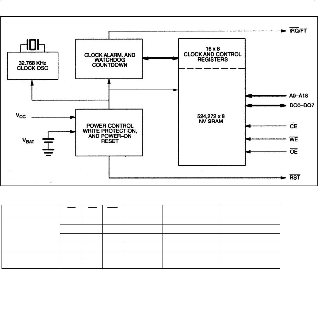
The DS1557 is a full-function, year-2000-compliant (Y2KC), real-time clock/calendar (RTC) with an
RTC alarm, watchdog timer, power-on reset, battery monitor, and 512k x 8 nonvolatile static RAM. User
access to all registers within the DS1557 is accomplished with a byte-wide interface as shown in Figure
1. The RTC registers contain century, year, month, date, day, hours, minutes, and seconds data in 24-hour
BCD format. Corrections for day of month and leap year are made automatically.
The RTC registers are double-buffered into an internal and external set. The user has direct access to the
external set. Clock/calendar updates to the external set of registers can be disabled and enabled to allow
the user to access static data. Assuming the internal oscillator is turned on, the internal set of registers is
continuously updated; this occurs regardless of external registers settings to guarantee that accurate RTC
information is always maintained.
The DS1557 has interrupt (IRQ/FT) and reset (RST) outputs which can be used to control CPU activity.
The IRQ/FT interrupt output can be used to generate an external interrupt when the RTC register values
match user programmed alarm values. The interrupt is always available while the device is powered from
the system supply and can be programmed to occur when in the battery-backed state to serve as a system
wakeup. Either the IRQ/FT or RST outputs can also be used as a CPU watchdog timer, CPU activity is
monitored and an interrupt or reset output will be activated if the correct activity is not detected within
programmed limits. The DS1557 power-on reset can be used to detect a system power down or failure
and hold the CPU in a safe reset state until normal power returns and stabilizes; the RST output is used
for this function.
The DS1557 also contains its own power-fail circuitry, which automatically deselects the device when the
V
CC
supply enters an out-of-tolerance condition. This feature provides a high degree of data security
during unpredictable system operation brought on by low V
CC
levels.
DS1557 4Meg, Nonvolatile, Y2K-Compliant Timekeeping RAM
3 of 17
Figure 1. Block Diagram
Table 1. Operating Modes
V
CC
CE OE WE
DQ0–DQ7 MODE POWER
V
IH
X X HIGH-Z Deselect Standby
V
IL
X V
IL
D
IN
Write Active
V
IL
V
IL
V
IH
D
OUT
Read Active
V
CC
> V
PF
V
IL
V
IH
V
IH
HIGH-Z Read Active
V
SO
< V
CC
<V
PF
X X X HIGH-Z Deselect CMOS Standby
V
CC
< V
SO
<V
PF
X X X HIGH-Z Data Retention Battery Current
DATA READ MODE
The DS1557 is in the read mode whenever CE (chip enable) is low and WE (write enable) is high. The
device architecture allows ripple-through access to any valid address location. Valid data will be available
at the DQ pins within t
AA
after the last address input is stable, providing that CE and OE access times are
satisfied. If CE or OE access times are not met, valid data will be available at the latter of chip enable
access (t
CEA
) or at output enable access time (t
OEA
). The state of the data input/output pins (DQ) is
controlled by CE and
OE
. If the outputs are activated before t
AA
, the data lines are driven to an
intermediate state until t
AA
. If the address inputs are changed while CE and OE remain valid, output data
will remain valid for output data hold time (tOH) but will then go indeterminate until the next address
access.
Maxim
DS1557

DS1557WP-120IND+

Mfr. #:
Manufacturer:
Maxim Integrated
Description:
Real Time Clock 4M NV RAM Timekeeper
Lifecycle:
New from this manufacturer.
Delivery:
DHL FedEx Ups TNT EMS
Payment:
T/T Paypal Visa MoneyGram Western Union

Products related to this Datasheet