LT3092
10
3092fc
For more information www.linear.com/LT3092
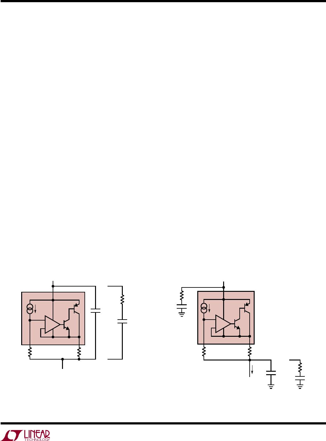
applicaTions inForMaTion
inductive components and may be complex distributed
networks. In addition, the current source’s value will dif-
fer between applications and its connection may be GND
referenced, power supply referenced or floating in a signal
line path. Linear T
echnology strongly recommends that
stability be tested in situ for any LT3092 application.
In
LT3092 applications with long wires or PCB traces, the
inductive reactance may cause instability. In some cases,
adding series resistance to the input and output lines (as
shown in Figure 2) may sufficiently dampen these possible
high-Q lines and provide stability. The user must evaluate
the required resistor values against the design’s headroom
constraints. In general, operation at low output current
levels (< 5mA) automatically requires higher values of
programming resistors and may provide the necessary
damping without additional series impedance.
If the line impedances in series with the LT3092 are
complex enough such that series damping resistors are
not sufficient, a frequency compensation network may be
necessary. Several options may be considered.
From this point, selecting R
OUT
is easy, as it is a straight-
forward calculation from R
SET
. Take note, however, resistor
errors must be accounted for as well. While larger voltage
drops across R
SET
minimize the error due to offset, they
also increase the required operating headroom.
Obtaining the best temperature coefficient does not require
the use of expensive resistors with low ppm temperature
coefficients. Instead, since the output current of the LT3092
is determined by the ratio of R
SET
to R
OUT
, those resistors
should have matching temperature characteristics. Less
expensive resistors made from the same material will
provide matching temperature coefficients. See resistor
manufacturers’ data sheets for more details.
Stability and Frequency Compensation
The LT3092 does not require input or output capacitors
for stability in many current-source applications. Clean,
tight PCB layouts provide a low reactance, well controlled
operating environment for the LT3092 without requiring
capacitors to frequency-compensate the circuit. The front
page Typical Application circuit illustrates the simplicity
of using the LT3092.
Some current source applications will use a capacitor
connected in parallel with the SET pin resistor to lower
the current source’s noise. This capacitor also provides a
soft-start function for the current source. This capacitor
connection is depicted in Figure 7 (see the Quieting the
Noise section).
When operating with a capacitor across the SET pin resis
-
tor, external compensation is usually required to maintain
stability and compensate for the introduced pole. The
following paragraphs discuss methods for stabilizing
the
LT3092 for either this capacitance or other complex
impedances that may be presented to the device. Linear
Technology strongly recommends testing stability in situ
with final components before beginning production.
Although the LT3092’s design strives to be stable without
any capacitors over a wide variety of operating conditions, it
is not possible to test for all possible combinations of input
and output impedances that the LT3092 will encounter.
These impedances may include resistive, capacitive and
Figure 2. Adding Series Resistor Decouples
and Dampens Long Line Reactances
IN
SET OUT
+
–
LT3092
10µA
R
SET
R
OUT
R
SERIES
R
SERIES
LONG LINE
REACTANCE/INDUCTANCE
3092 F02
LONG LINE
REACTANCE/INDUCTANCE