AD421
12
REV. C
DV
DD
AV
DD
REF IN
CS
DATA OUT
SCLK
DATA IN
AGND
DGND
MCLK IN
MCLK OUT
AD7714/
AD7715
ANALOG
TO
DIGITAL
CONVERTER
SENSORS
RTD
mV TC
REF OUT1
BOOST
V
CC
LV
COMP
DRIVE
LOOP
RTN
REF OUT2
REF IN
CLOCK
LATCH
DATA
COM
C1 C2
C3
LOOP
POWER
0.01F
DN25D
2.2F
3.3V
1.25V
4.7F
AMBIENT
TEMP
SENSOR
AD421
MICROCONTROLLER
V
CC
GND
WAVEFORM
SHAPER
BANDPASS
FILTER
HART
MODEM
BELL 202
0.1F
0.01F
1k
1000pF
C
C
*
HT20C12/20C15
4.7F100k
*FOR SELECTION OF C
C
, REFER TO AN-534
Figure 17. AD421 in HART Transmitter Application
across R2. The ratio of R1 to R2 determines the current that
flows in the load resistor R
L
. I
L
= [1 + R1/R2] × I
PROG
, where I
L
is the current that flows in the load resistor R
L
and I
PROG
is the
current programmed to the AD421. R1 and R2 are external to
the AD421 and will need to be matched resistors to obtain a
highly accurate current source.
Current Source
Figure 18 shows an application circuit for the AD421 being
used as a current source. The current programmed to the
AD421 (4 mA to 20 mA) will develop a voltage across R1.
This same voltage due to negative feedback will be generated
LOOP
RTN
R2
R
L
R1
C1 C2
C3
COM
V
CC
LV
2.2F
COM
DRIVE
COMP
BOOST
0.01F
0.01F
0.0033F
LATCH
CLOCK
DATA
REF IN
REF OUT2
REF OUT1
4.7F
COM
AD421
+5V
10k
10k
10k
CLOCK
LATCH
DATA
V
S
RETURN
5 VOLT
REGULATOR
OUT IN
V
S
COM
Figure 18. AD421 in Programmable Current Source/Sink
AD421
13
REV. C
Battery Backup
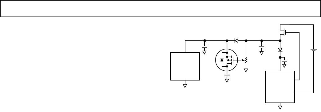
Figure 19 shows an application circuit for the AD421 where the
micro and memory sections of the circuitry are protected against
losing data if the loop is broken. The backup circuit switches
from V
CC
to battery voltage without a glitch when V
CC
power is
lost. The IRFF9113 acts as a current source during normal
operation and provides a constant charging current to the supercap
or Nicad. The loss of V
CC
drops the IRFF9113’s gate voltage to
zero volts, which allows the battery or supercaps current to flow
through the MOSFETs channel and integral body diode to
provide power for the micro and memory sections. To calibrate
this circuit, connect an ammeter in series with the battery or
supercap. Then with V
CC
and the load present adjust the 100 k
potentiometer for the battery charging current recommended by
the battery or supercap manufacturer.
Nonrechargeable batteries should not be used in this application
due to danger of explosion.
100k
IN3611
IN3611
DN25D
V
CC
DRIVE
LOOP
RTN
COM
AD421*
V
LOOP
IRFF9113
SUPERCAP
V
CC
GND
MICRO/
MEMORY
*ADDITIONAL CIRCUITRY OMITTED FOR CLARITY
4.7F0.1F
2.2F
Figure 19. Battery Backup Circuit
AD421
14
REV. C
OUTLINE DIMENSIONS
Dimensions shown in inches and (mm).
16-Lead Plastic DIP
(N-16)
16
18
9
0.840 (21.34)
0.745 (18.92)
0.280 (7.11)
0.240 (6.10)
PIN 1
SEATING
PLANE
0.022 (0.558)
0.014 (0.356)
0.060 (1.52)
0.015 (0.38)
0.210 (5.33)
MAX
0.130
(3.30)
MIN
0.070 (1.77)
0.045 (1.15)
0.100
(2.54)
BSC
0.160 (4.06)
0.115 (2.93)
0.325 (8.26)
0.300 (7.62)
0.015 (0.381)
0.008 (0.204)
0.195 (4.95)
0.115 (2.93)
16-Lead (Wide Body) Small Outline Package
(R-16)
0.2992 (7.60)
0.2914 (7.40)
16 9
81
0.4133 (10.50)
0.3977 (10.00)
0.4193 (10.65)
0.3937 (10.00)
PIN 1
SEATING
PLANE
0.0118 (0.30)
0.0040 (0.10)
0.0192 (0.49)
0.0138 (0.35)
0.1043 (2.65)
0.0926 (2.35)
0.0500
(1.27)
BSC
0.0125 (0.32)
0.0091 (0.23)
0.0500 (1.27)
0.0157 (0.40)
0.0291 (0.74)
0.0098 (0.25)
x 45
8
0
PRINTED IN U.S.A.
C2105b03/00 (rev. C)

AD421BNZ

Mfr. #:
Manufacturer:
Analog Devices Inc.
Description:
Digital to Analog Converters - DAC IC 16-BIT
Lifecycle:
New from this manufacturer.
Delivery:
DHL FedEx Ups TNT EMS
Payment:
T/T Paypal Visa MoneyGram Western Union