HN (AHN)
–6–
ASCTB5E 201408-T
NOTES
1. For cautions for use, please read
“General Application Guidelines”.
2. Coil applied voltage
To ensure proper operation, the voltage
applied to both terminals of the coil
should be ±5% (at 20°C 68°F) the rated
operating voltage of the coil.
Also, be aware that the pick-up and drop-
out voltages will fluctuate depending on
the ambient temperature and operating
conditions.
3. LED indications
The light of the light emitting diode is
what displays operation. If voltage
remains after relay dropout, the LED
might illuminate briefly.
4. Switching lifetime
The switching lifetime is defined under
the standard test condition specified in
the JIS C 5442(*2) standard (temperature
15 to 35°C 59 to 95°F, humidity 25 to
75% R.H.). Check this with the real
device as it is affected by coil driving
circuit, load type, activation frequency,
activation phase,ambient conditions and
other factors.
Also, be especially careful of loads such
as those listed below.
1) When used for AC load-operating and
the operating phase is synchronous.
Rocking and fusing can easily occur due
to contact shifting.
2) High-frequency load-operating
When high-frequency opening and
closing of the relay is performed with a
load that causes arcs at the contacts,
nitrogen and oxygen in the air is fused by
the arc energy and HNO
3 is formed. This
can corrode metal materials.
Three countermeasures for these are
listed here.
(1) Incorporate an arc-extinguishing
circuit.
(2) Lower the operating frequency
(3) Lower the ambient humidity
5. Direct mount type (TM type)
If the current to the connection terminal
will exceed 10 A, we recommend
connecting with solder. If you are going to
use a tab terminal when the current will
exceed 10 A, make sure to verify the
temperature rise on the receptacle side
under actual conditions before using.
Please be careful, because excessive
stress on the TM terminal can cause
fluctuations in characteristics and
damage.
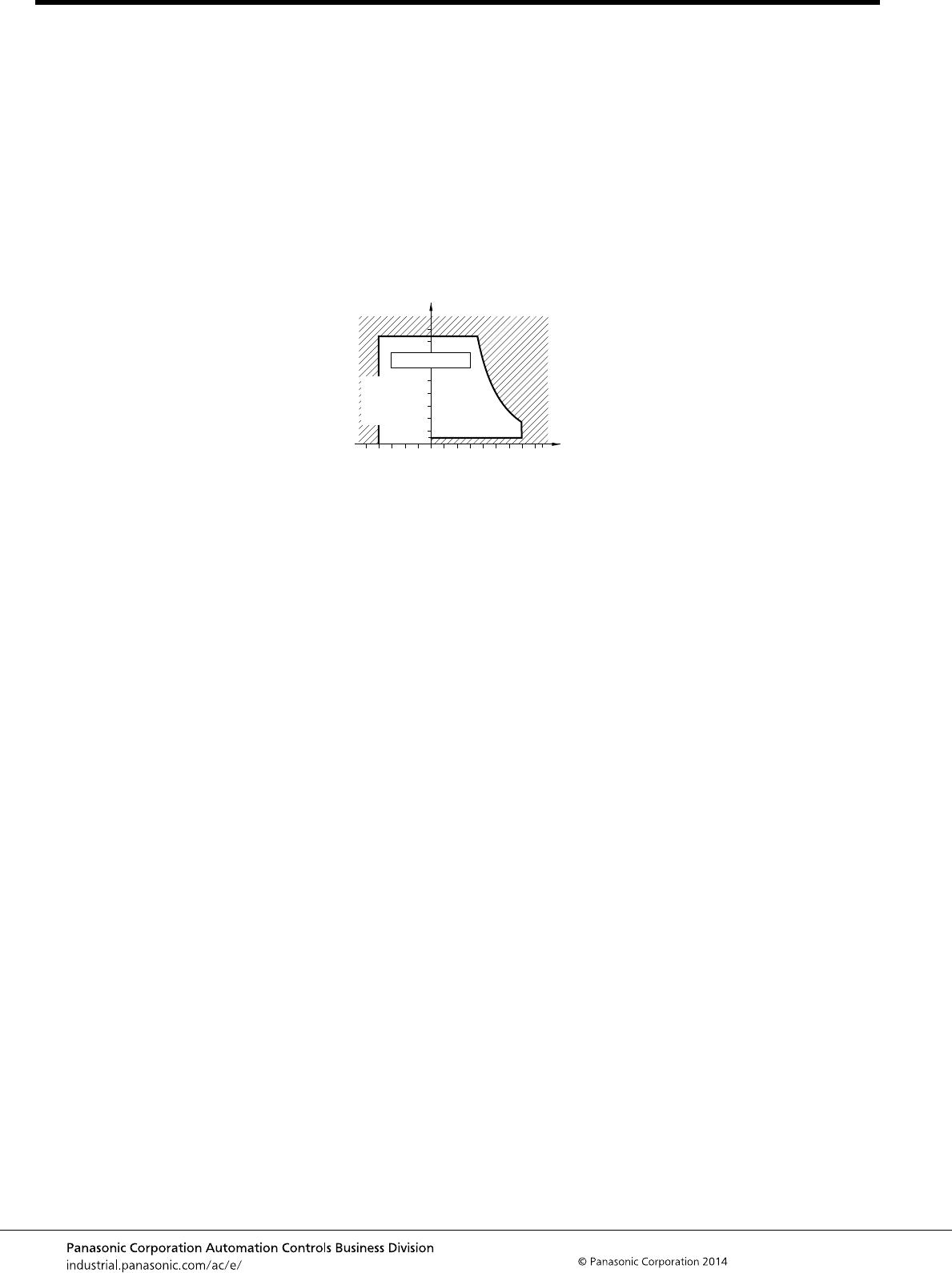
6. Conditions for operation, transport
and storage
1) Ambient temperature, humidity, and
atmospheric pressure during usage,
transport, and storage of the relay:
(1) Temperature:
–40 to +70°C – 40 to +158°F
(2) Humidity: 5 to 85% RH
(Avoid freezing and condensation.)
The humidity range varies with the
temperature. Use within the range
indicated in the graph below.
Temperature and humidity range for
usage, transport, and storage
(3) Atmospheric pressure: 86 to 106 kPa
2) Condensation
Condensation forms when there is a
sudden change in temperature under
high temperature and high humidity
conditions. Condensation will cause
deterioration of the relay insulation.
3) Freezing
Condensation or other moisture may
freeze on the relay when the
temperatures is lower than 0°C 32°F. This
causes problems such as sticking of
movable parts or operational time lags.
4) Low temperature, low humidity
environments
The plastic becomes brittle if the relay is
exposed to a low temperature, low
humidity environment for long periods of
time.
7. Diode characteristics
1) Reverse breakdown voltage:
Min. 1,000V (with diode type)
Min. 400V (with diode and LED indication
type)
8. Diode type
Since the diode inside the relay coil are
designed to absorb the counter emf, the
element may be damaged if a large
surge, etc., is applied to the diode.
If there is the possibility of a large surge
voltage from the outside, please
implement measures to absorb it.
9. Please connect DC coil types with
LED and built-in diode correctly by
verifying the coil polarity (“+” and “–
”). Connecting with reverse polarity
will cause the LED not to light and
damage the built-in diode due to its
specification.
10. Installation
If you will be installing adjacent to other
relays, please keep a distance of at least
5 mm from the relay.
Humidity, %R.H.
Tolerance range
85
5
070–40
+32 +158–40
(Avoid
condensation
when used at
temperatures
higher than
0°C
(Avoid freezing
when used at
temperatures
lower than
0°C 32°F)
Temperature, °C °F
32°F)