Tsi721 Datasheet 24 April 4, 2016
Integrated Device Technology
I2C_SEL IO I
2
C pin select. Combined with the I2C_SA[1,0] pins, Tsi721 will determine the
lower 2 bits of the 7-bit address of the EEPROM address it boots from.
When asserted, the I2C_SA[1:0] pins represent the two LSBs of the 7-bit
EEPROM slave address when Tsi721 acts as a I
2
C master downloading from an
EEPROM. The EEPROM slave address is as follows:
A6 = 1
A5 = 0
A4 = 1
A3 = 0
A2 = 0
A1 = I2C_SA[1]
A0 = I2C_SA[0]
When de-asserted, the I2C_SA[1:0] pins are ignored and the lower two bits of
the EEPROM address default to 00. The values of the EEPROM address can be
overridden by software after initialization.
This power-up signal is multiplexed with GPIO[5]. It is a static signal.
SP_DEVID IO S-RIO base deviceID control
When the SP_HOST pin is high, it configures the reset value of the RapidIO
Base deviceID CSR: the LSB of the CSR’s BASE_ID and LAR_BASE_ID fields
are set to SP_DEVID, while other bits of these fields are set to 0.
When the SP_HOST pin is low and SP_DEVID is high, it configures the reset
value of the RapidIO Base deviceID CSR: the CSR’s BASE_ID and
LAR_BASE_ID fields are set to all ones.
When the SP_HOST pin is low and SP_DEVID is low, it configures the reset
value of the RapidIO Base deviceID CSR: the CSR’s BASE_ID field is set to
0xFE and the CSR’s LAR_BASE_ID field are set to 0x00FE.
This signal is multiplexed with GPIO[10]. It is a static signal.
SP_HOST IO S-RIO host / slave control. This signal sets the reset value of the HOST bit of the
RapidIO Port General Control CSR.
0 = Tsi721 is an S-RIO slave.
1 = Tsi721 is an S-RIO host.
This signal is multiplexed with GPIO[9]. It is a static signal.
SP_SWAP_RX IO S-RIO receive lane swap. This signal sets the reset value of the SWAP_RX[1:0]
bits of RapidIO PLM Port Implementation Specific Control Register.
0 = Disable S-RIO port receive lane swap; that is, set the SWAP_RX[1:0]
register bits to 0b00.
1 = Enable S-RIO port receive 4x lane swap; that is, set the SWAP_RX[1:0]
register bits to 0b10.
This signal is multiplexed with GPIO[7].
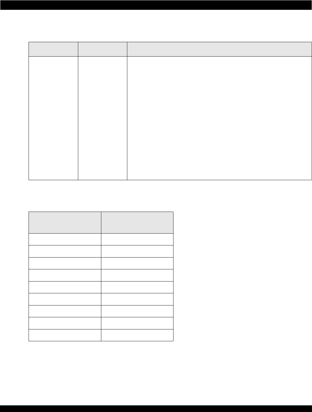
Table 9: Power-Up Signals (Continued)
Name Pin Type Description