Expand menu
Hello, Sign in
My Account
0
Cart
Home
Products
Sensors
Semiconductors
Passive Components
Connectors
Power
Electromechanical
Optoelectronics
Circuit Protection
Integrated Circuits - ICs
Main Products
Manufacturers
Blog
Services
About OMO
About Us
Contact Us
Check Stock
ACPL-M71U-000E
P1-P3
P4-P6
P7-P9
P10-P11
10
GND2
0.1 μF
Bypass Cap
OUTPUT Vo
MONITORING
NODE
SHIELD
1
3
6
4
5
Rin=700
Vdd=5 V
C
L
=15pF
ACPL-M72U
GND1
INPUT
MONITORING
NODE
PULSE GEN.
0
V
O
t
PHL
t
PLH
80% V
dd
V
dd
V
OL
V
in
2
V
in
2
0.8 V
V
in
GND2
0.1 μF
Bypass Cap
OUTPUT Vo
MONITORING
NODE
SHIELD
+
−
1
3
6
4
5
R1=350
Vdd=5 V
R2=350
High Voltage Pulse
V
CM
= 1000V
C
L
=15pF
ACPL-M72U
GND2
0.1 μF
Bypass Cap
OUTPUT Vo
MONITORING
NODE
SHIELD
+
−
1
3
6
4
5
R1=350
Vdd=5 V
R2=350
High Voltage Pulse
V
CM
= 1000V
C
L
=15pF
ACPL-M72U
Vin =
4.5 - 5.5V
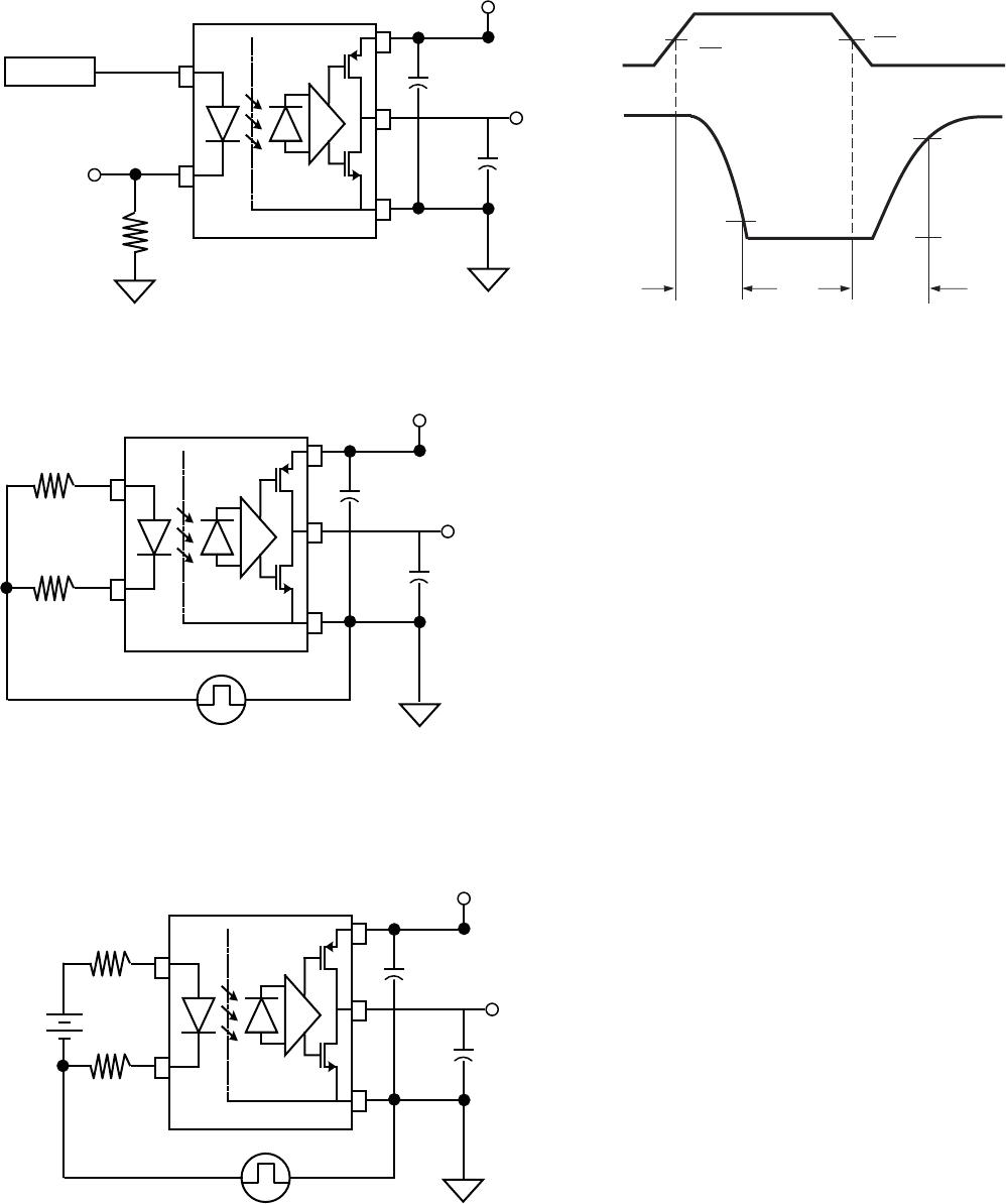
Figure 15. Low P
ower Mode High CMR, CMH
Test Circuit
Figure 16. Low P
ower Mode High CMR, CML
Test Circuit
ACPL
-M72U Low P
ow
er Mode:
Figure 14. Low P
ow
er Mode Switching T
est Circuit and Typical W
av
eform
For pr
oduct information and a complete list of distributors
, please go to our web sit
e:
ww
w.a
vagotech.com
Av
ago
, Avago
T
echnologies, the A logo and R
2
Coupler™ ar
e trademarks of A
vago
T
echnologies in the United States and other countries
.
Data subject to change. C
opyright © 2005-2012 A
vago T
echnologies. All rights reserved.
A
V02-3712EN - Oc
tober 5, 2012
LOGIC I/O
Vdd
Ro
GND2
0.1 μF
Bypass Cap
Vout
GND1
Vin
SHIELD
½R
LIMIT
½R
LIMIT
LOGIC I/O
Cin
Vdd
Ro
GND2
0.1 μF
Bypass Cap
Vout
GND1
Vin
SHIELD
R
LIMIT
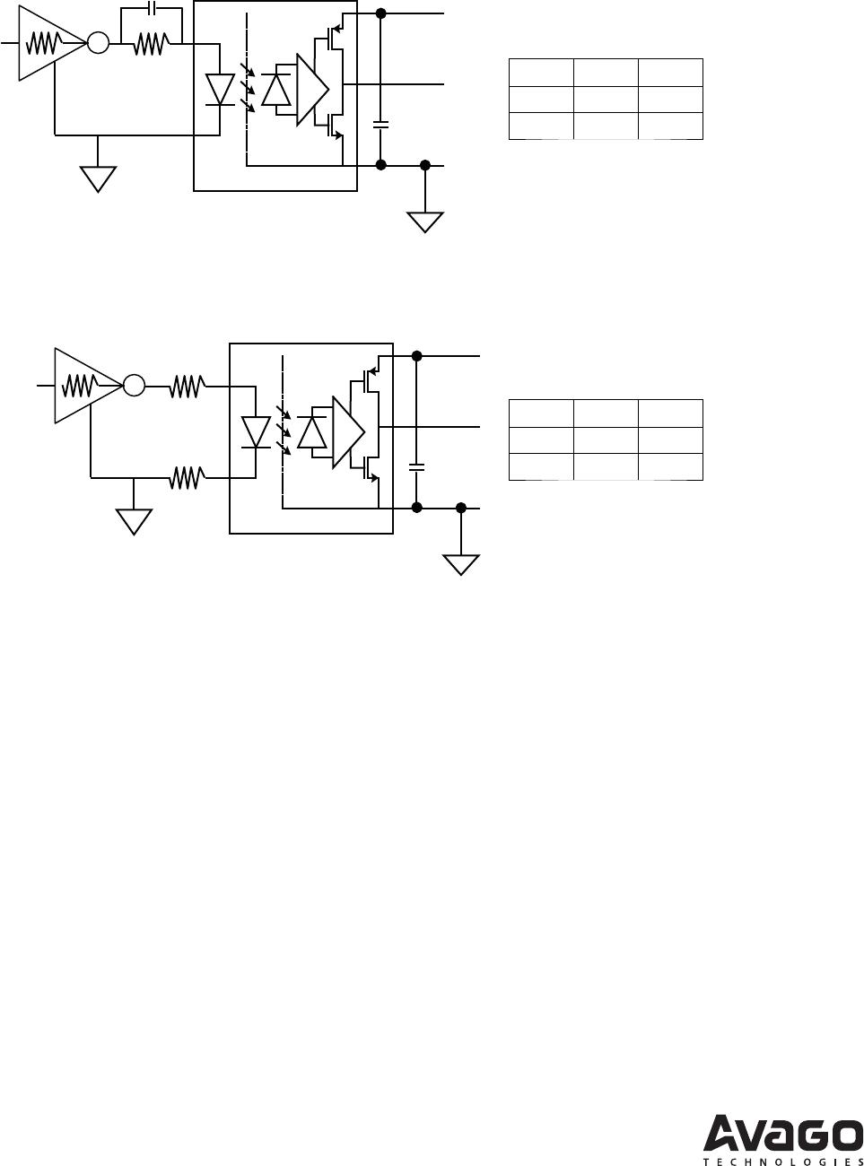
Application Circ
uits
Figure 17. Recommended Application Circuit for ACPL
-M71U High S
peed Performance
Figure 18. Recommended Application Circuit for ACPL
-M72U Low Pow
er Performance
T
ruth Table
Vin
LED
Vout
LO
NL
H
OFF
H
T
ruth Table
Vin
LED
Vout
LO
NL
H
OFF
H
P1-P3
P4-P6
P7-P9
P10-P11
ACPL-M71U-000E
Mfr. #:
Buy ACPL-M71U-000E
Manufacturer:
Broadcom / Avago
Description:
High Speed Optocouplers Optocoupler
Lifecycle:
New from this manufacturer.
Delivery:
DHL
FedEx
Ups
TNT
EMS
Payment:
T/T
Paypal
Visa
MoneyGram
Western
Union
Products related to this Datasheet
ACPL-M71U-000E
ACPL-M71U-500E
ACPL-M72U-000E
ACPL-M72U-500E