MP1584
3A, 1.5MHz, 28V
Step-Down Converter
MP1584 Rev. 1.0 www.MonolithicPower.com 1
8/8/2011 MPS Proprietary Information. Unauthorized Photocopy and Duplication Prohibited.
© 2011 MPS. All Rights Reserved.
The Future of Analog IC Technology
DESCRIPTION
The MP1584 is a high frequency step-down
switching regulator with an integrated internal
high-side high voltage power MOSFET. It
provides 3A output with current mode control for
fast loop response and easy compensation.
The wide 4.5V to 28V input range accommodates
a variety of step-down applications, including
those in an automotive input environment. A
100µA operational quiescent current allows use in
battery-powered applications.
High power conversion efficiency over a wide
load range is achieved by scaling down the
switching frequency at light load condition to
reduce the switching and gate driving losses.
The frequency foldback helps prevent inductor
current runaway during startup and thermal
shutdown provides reliable, fault tolerant
operation.
By switching at 1.5MHz, the MP1584 is able to
prevent EMI (Electromagnetic Interference) noise
problems, such as those found in AM radio and
ADSL applications.
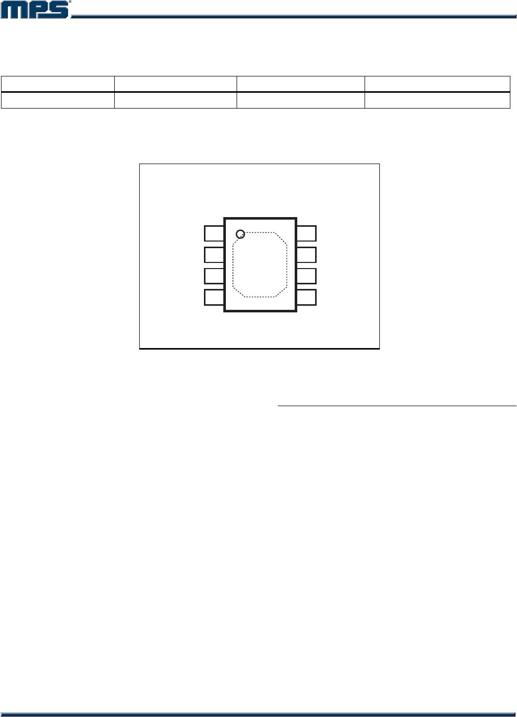
The MP1584 is available in a thermally enhanced
SOIC8E package.
FEATURES
Wide 4.5V to 28V Operating Input Range
Programmable Switching Frequency from
100kHz to 1.5MHz
High-Efficiency Pulse Skipping Mode for
Light Load
Ceramic Capacitor Stable
Internal Soft-Start
Internally Set Current Limit without a
Current Sensing Resistor
Available in SOIC8E Package.
APPLICATIONS
High Voltage Power Conversion
Automotive Systems
Industrial Power Systems
Distributed Power Systems
Battery Powered Systems
“MPS” and “The Future of Analog IC Technology” are Registered Trademarks of
Monolithic Power Systems, Inc.
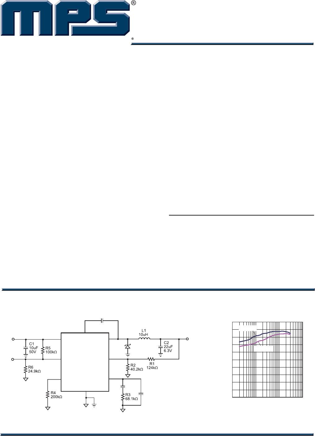
TYPICAL APPLICATION
C3
220pF
C6
NS
C4
100nF
D1
V
OUT
3.3V
V
IN
VIN
EN
FREQ
GND
BST
5
8
1
4
3
7
2
6
SW
FB
COMP
MP1584
EN
OUTPUT CURRENT (A)
EFFICIENCY (%)
0
10
20
30
40
50
60
70
80
90
100
0.01 0.1 1 10
V
IN
=12V
V
IN
=24V
Efficiency Curve
(f
SW
=500kHz)
MP1584 – 3A, 1.5MHz, 28V STEP-DOWN CONVERTER
MP1584 Rev. 1.0 www.MonolithicPower.com 2
8/8/2011 MPS Proprietary Information. Unauthorized Photocopy and Duplication Prohibited.
© 2011 MPS. All Rights Reserved.
ORDERING INFORMATION
* For Tape & Reel, add suffix –Z (e.g. MP1584EN–Z);
For RoHS Compliant Packaging, add suffix –LF. (e.g. MP1584EN–LF–Z)
PACKAGE REFERENCE
SW
EN
COMP
FB
BST
VIN
FREQ
GND
1
2
3
4
8
7
6
5
TOP VIEW
ABSOLUTE MAXIMUM RATINGS
(1)
Supply Voltage (V
IN
) ..................... –0.3V to +30V
Switch Voltage (V
SW
) ............ –0.3V to V
IN
+ 0.3V
BST to SW ..................................... –0.3V to +6V
All Other Pins ................................. –0.3V to +6V
Continuous Power Dissipation (T
A
=
+25°C)
(2)
............................................................. 2.5W
Junction Temperature ............................... 150C
Lead Temperature .................................... 260C
Storage Temperature .............. –65°C to +150C
Recommended Operating Conditions
(3)
Supply Voltage V
IN
........................... 4.5V to 28V
Output Voltage V
OUT
......................... 0.8V to 25V
Operating Junct. Temp (T
J
) ..... –20C to +125C
Thermal Resistance
(4)
θ
JA
θ
JC
SOIC8E .................................. 50 ...... 10 ... C/W
Notes:
1) Exceeding these ratings may damage the device.
2) The maximum allowable power dissipation is a function of the
maximum junction temperature T
J
(MAX), the junction-to-
ambient thermal resistance
JA
, and the ambient temperature
T
A
. The maximum allowable continuous power dissipation at
any ambient temperature is calculated by P
D
(MAX)=(T
J
(MAX)-
T
A
)/
JA
. Exceeding the maximum allowable power dissipation
will cause excessive die temperature, and the regulator will go
into thermal shutdown. Internal thermal shutdown circuitry
protects the device from permanent damage.
3) The device is not guaranteed to function outside of its
operating conditions.
4) Measured on JESD51-7, 4-layer PCB.
Part Number* Package Top Marking Free Air Temperature (T
A
)
MP1584EN
SOIC8E
MP1584EN
–20C to +85C
MP1584 – 3A, 1.5MHz, 28V STEP-DOWN CONVERTER
MP1584 Rev. 1.0 www.MonolithicPower.com 3
8/8/2011 MPS Proprietary Information. Unauthorized Photocopy and Duplication Prohibited.
© 2011 MPS. All Rights Reserved.
ELECTRICAL CHARACTERISTICS
V
IN
= 12V, V
EN
= 2.5V, V
COMP
= 1.4V, T
A
= +25C, unless otherwise noted.
Parameter Symbol Condition Min Typ Max Units
Feedback Voltage V
FB
4.5V < V
IN
< 28V 0.776 0.8 0.824 V
Upper Switch On Resistance R
DS
(
ON
)
V
BST
– V
SW
= 5V 150 m
Upper Switch Leakage V
EN
= 0V, V
SW
= 0V, V
IN
= 28V 1 A
Current Limit 4.0 4.7 A
COMP to Current Sense
Transconductance
G
CS
9 A/V
Error Amp Voltage Gain
(
5
)
200 V/V
Error Amp Transconductance I
COMP
= ±3µA 40 60 80 µA/V
Error Amp Min Source current V
FB
= 0.7V 5 µA
Error Amp Min Sink current V
FB
= 0.9V –5 µA
VIN UVLO Threshold 2.7 3.0 3.3 V
VIN UVLO Hysteresis 0.35 V
Soft-Start Time
(
5
)
0V < V
FB
< 0.8V 1.5 ms
Oscillator Frequency R
FREQ
= 100k 900 kHz
Shutdown Supply Current V
EN
= 0V 12 20 µA
Quiescent Supply Current No load, V
FB
= 0.9V 100 125 µA
Thermal Shutdown 150
C
Thermal Shutdown Hysteresis 15
C
Minimum Off Time
(
5
)
100 ns
Minimum On Time
(
5
)
100 ns
EN Up Threshold 1.35 1.5 1.65 V
EN Hysteresis 300 mV
Note:
5) Guaranteed by design.

MP1584EN-LF-Z

Mfr. #:
Manufacturer:
Monolithic Power Systems (MPS)
Description:
Switching Voltage Regulators 3A 1.5MHz 28V Nonsync Buck
Lifecycle:
New from this manufacturer.
Delivery:
DHL FedEx Ups TNT EMS
Payment:
T/T Paypal Visa MoneyGram Western Union

Products related to this Datasheet