74HC161 All information provided in this document is subject to legal disclaimers. © NXP Semiconductors N.V. 2017. All rights reserved.
Product data sheet Rev. 3 — 4 January 2017 9 of 20
NXP Semiconductors
74HC161
Presettable synchronous 4-bit binary counter; asynchronous reset
t
W
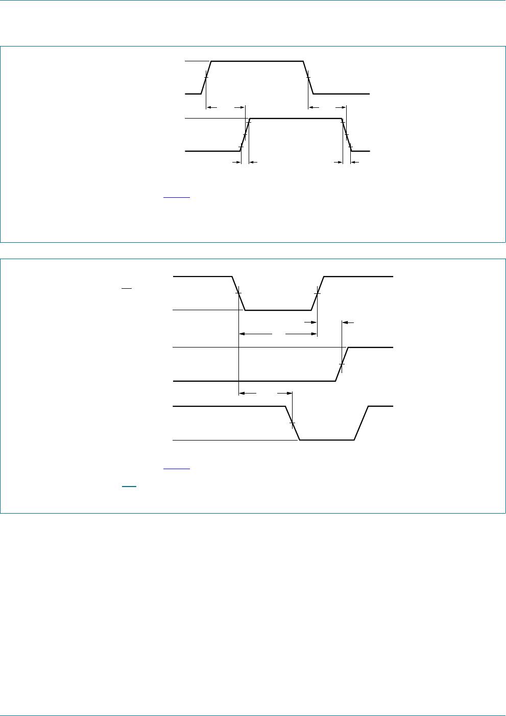
pulse width CP; HIGH or LOW;
see Figure 9
V
CC
= 2.0 V 80 22 - 100 - 120 - ns
V
CC
=4.5V 16 8 - 20 - 24 - ns
V
CC
=6.0V 14 6 - 17 - 20 - ns
MR
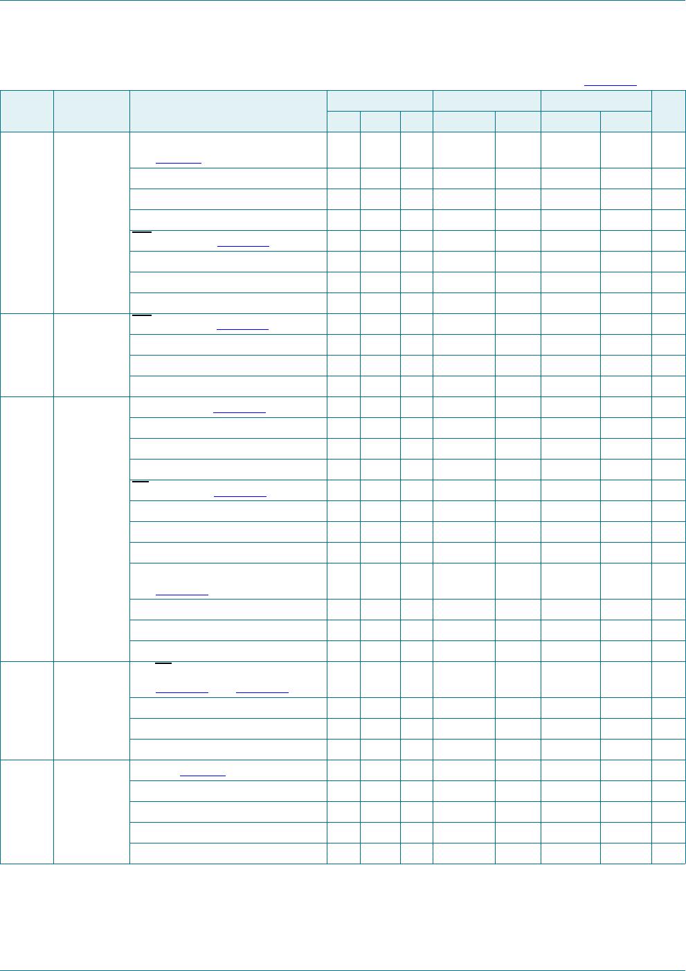
; LOW; see Figure 11
V
CC
= 2.0 V 80 19 - 100 - 120 - ns
V
CC
=4.5V 16 7 - 20 - 24 - ns
V
CC
=6.0V 14 6 - 17 - 20 - ns
t
rec
recovery
time
MR to CP; see Figure 11
V
CC
= 2.0 V 100 19 - 125 - 150 - ns
V
CC
=4.5V 20 7 - 25 - 30 - ns
V
CC
=6.0V 17 6 - 21 - 26 - ns
t
su
set-up time Dn to CP; see Figure 12
V
CC
= 2.0 V 80 25 - 100 - 120 - ns
V
CC
=4.5V 16 9 - 20 - 24 - ns
V
CC
=6.0V 14 7 - 17 - 20 - ns
PE
to CP; see Figure 12
V
CC
= 2.0 V 100 30 - 125 - 150 - ns
V
CC
=4.5V 20 11 - 25 - 30 - ns
V
CC
=6.0V 17 9 - 21 - 26 - ns
CEP, CET to CP;
see Figure 13
V
CC
= 2.0 V 170 47 - 215 - 255 - ns
V
CC
=4.5V 34 17 - 43 - 51 - ns
V
CC
=6.0V 29 14 - 37 - 43 - ns
t
h
hold time Dn, PE, CEP, CET to CP;
see Figure 12
and Figure 13
V
CC
=2.0V 0 14 - 0 - 0 - ns
V
CC
=4.5V 0 5- 0 - 0 -ns
V
CC
=6.0V 0 4- 0 - 0 -ns
f
max
maximum
frequency
CP; see Figure 9
V
CC
= 2.0 V 4.6 13 - 3.6 - 3.0 - MHz
V
CC
=4.5V 23 40 - 18 - 15 - MHz
V
CC
= 5.0 V; C
L
=15pF - 44 - - - - - MHz
V
CC
=6.0V 27 48 - 21 - 18 - MHz
Table 7. Dynamic characteristics
…continued
Voltages are referenced to GND (ground = 0 V); C
L
= 50 pF unless otherwise specified; for test circuit see Figure 14.
Symbol Parameter Conditions 25 C 40 C to +85 C 40 C to +125 C Unit
Min Typ Max Min Max Min Max