This is information on a product in full production.
September 2015 DocID13862 Rev 3 1/18
L6384E
High voltage half-bridge driver
Datasheet - production data
Features
High voltage rail up to 600 V
dV/dt immunity ± 50 V/nsec in full temperature
range
Driver current capability
400 mA source
650 mA sink
Switching times 50/30 nsec rise/fall with 1 nF
load
CMOS/TTL Schmitt trigger inputs with
hysteresis and pull-down
Shutdown input
Deadtime setting
Undervoltage lockout
Integrated bootstrap diode
Clamping on V
CC
Available in DIP-8/SO-8 packages
Applications
Home appliances
Induction heating
HVAC
Industrial applications and drives
Motor drivers
DC, AC, PMDC and PMAC motors
Lighting applications
Factory automation
Power supply systems
Description
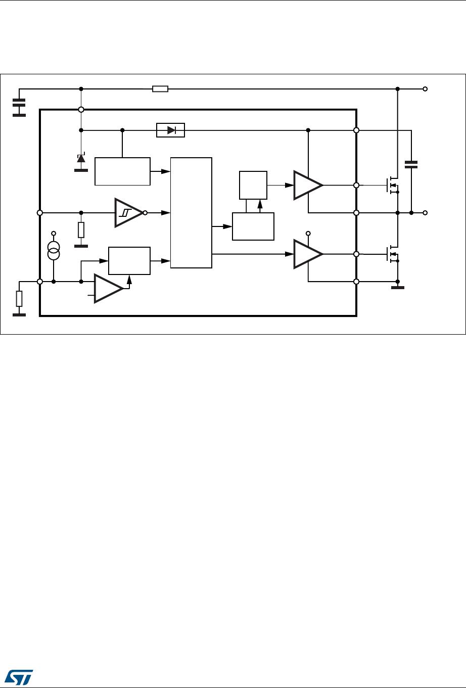
The L6384E is a high voltage gate driver,
manufactured with the BCD™ “offline”
technology, and able to drive a half-bridge of
power MOSFET or IGBT devices. The high-side
(floating) section is able to work with voltage rail
up to 600 V. Both device outputs can sink and
source 650 mA and 400 mA respectively and
cannot be simultaneously driven high thanks to
single input configuration. Further prevention
from outputs cross conduction is guaranteed by
the deadtime function, tunable by the user
through an external resistor connected to the
DT/SD pin.
The L6384E device has one input pin, one enable
pin (DT/SD) and two output pins, and guarantees
matched delays between low-side and high-side
sections, thus simplifying device's high frequency
operation. The logic inputs are CMOS/TTL
compatible to ease the interfacing with controlling
devices. The bootstrap diode is integrated inside
the device, allowing a more compact and reliable
solution.
The L6384E features the UVLO protection and
a voltage clamp on the V
CC
supply voltage. The
voltage clamp is typically around 15.6 V and is
useful in order to ensure a correct device
functioning in cases where V
CC
supply voltage is
ramped up too slowly or is subject to voltage
drops.
The device is available in a DIP-8 tube and SO-8
tube and tape and reel packaging options.
DIP-8 SO-8
www.st.com
Contents L6384E
2/18 DocID13862 Rev 3
Contents
1 Block diagram . . . . . . . . . . . . . . . . . . . . . . . . . . . . . . . . . . . . . . . . . . . . . . 3
2 Electrical data . . . . . . . . . . . . . . . . . . . . . . . . . . . . . . . . . . . . . . . . . . . . . . 4
2.1 Absolute maximum ratings . . . . . . . . . . . . . . . . . . . . . . . . . . . . . . . . . . . . . 4
2.2 Thermal data . . . . . . . . . . . . . . . . . . . . . . . . . . . . . . . . . . . . . . . . . . . . . . . 4
2.3 Recommended operating conditions . . . . . . . . . . . . . . . . . . . . . . . . . . . . . 5
3 Pin connection . . . . . . . . . . . . . . . . . . . . . . . . . . . . . . . . . . . . . . . . . . . . . . 6
4 Electrical characteristics . . . . . . . . . . . . . . . . . . . . . . . . . . . . . . . . . . . . . 7
4.1 AC operation . . . . . . . . . . . . . . . . . . . . . . . . . . . . . . . . . . . . . . . . . . . . . . . 7
4.2 DC operation . . . . . . . . . . . . . . . . . . . . . . . . . . . . . . . . . . . . . . . . . . . . . . . 7
4.3 Timing diagram . . . . . . . . . . . . . . . . . . . . . . . . . . . . . . . . . . . . . . . . . . . . . . 8
5 Bootstrap driver . . . . . . . . . . . . . . . . . . . . . . . . . . . . . . . . . . . . . . . . . . . . 9
C
BOOT
selection and charging . . . . . . . . . . . . . . . . . . . . . . . . . . . . . . . . . . . . . . . . 9
6 Typical characteristic . . . . . . . . . . . . . . . . . . . . . . . . . . . . . . . . . . . . . . . 11
7 Package information . . . . . . . . . . . . . . . . . . . . . . . . . . . . . . . . . . . . . . . . 13
7.1 DIP-8 package information . . . . . . . . . . . . . . . . . . . . . . . . . . . . . . . . . . . . 13
7.2 SO-8 package information . . . . . . . . . . . . . . . . . . . . . . . . . . . . . . . . . . . . 15
8 Order codes . . . . . . . . . . . . . . . . . . . . . . . . . . . . . . . . . . . . . . . . . . . . . . . 17
9 Revision history . . . . . . . . . . . . . . . . . . . . . . . . . . . . . . . . . . . . . . . . . . . 17
DocID13862 Rev 3 3/18
L6384E Block diagram
18
1 Block diagram
Figure 1. Block diagram
LOGIC
UV
DETECTION
LEVEL
SHIFTER
RS
V
CC
LVG
DRIVER
V
CC
IN
DT/SD
V
BOOT
HVG
DRIVER
HVG
H.V.
LOAD
OUT
LVG
GND
D97IN518A
DEAD
TIME
V
CC
Idt
Vthi
BOOTSTRAP DRIVER
C
BOOT
4
3
5
6
7
8
1
2

L6384E

Mfr. #:
Manufacturer:
STMicroelectronics
Description:
Gate Drivers HV H-Bridge drive
Lifecycle:
New from this manufacturer.
Delivery:
DHL FedEx Ups TNT EMS
Payment:
T/T Paypal Visa MoneyGram Western Union

Products related to this Datasheet