Expand menu
Hello, Sign in
My Account
0
Cart
Home
Products
Sensors
Semiconductors
Passive Components
Connectors
Power
Electromechanical
Optoelectronics
Circuit Protection
Integrated Circuits - ICs
Main Products
Manufacturers
Blog
Services
About OMO
About Us
Contact Us
Check Stock
L6384E
P1-P3
P4-P6
P7-P9
P10-P12
P13-P15
P16-P18
Bootstrap driv
er
L6384E
10/18
DocID13862 Rev 3
For example: using a power MOSFET with a tot
al gate charge of 30 n
C, the drop on the
bootstrap DMOS is a
bout 1 V
, if the T
charge
is 5
s. In fact:
Equation 3
V
drop
has to be taken into account when
the voltage drop on C
BOOT
is calculated: if this drop
is too high, or the circuit topology doesn’t allo
w a suf
ficient chargin
g time, an external diode
can be used.
Figure 4. Boot
strap driver
V
drop
3
0nC
5
s
--------------
-
125
0.8
V
=
TO LOAD
D99IN1067
H.V.
HVG
ab
LVG
HVG
LVG
C
BOOT
TO LOAD
H.V.
C
BOOT
D
BOOT
V
BOOT
V
S
V
S
V
OUT
V
BOOT
V
OUT
DocID13862 Rev 3
1
1/18
L6384E
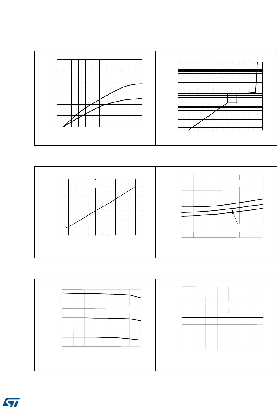
Typical characte
ristic
18
6 T
ypical
characteristic
Figure 5. T
ypical rise and fall times
vs. load cap
acit
ance
Figure 6. Quiescent curren
t vs. supply
volt
age
Figure 7. Dead
time vs. resist
ance
Figure 8. Driver propagatio
n delay
vs. temperature
Figure 9. Dead
time vs. temperature
Figure 10. Shut
down threshold
vs. temperature
For both high and low side buffers @25˚C Tamb
0
1
2
3
4
5
C (nF)
0
50
100
150
200
250
time
(nsec)
Tr
D99IN1015
Tf
02468
1
0
1
2
1
4
V
S
(V)
10
10
2
10
3
10
4
Iq
(
μ
A)
D99IN1016
50
100
150
200
250
300
0.0
0.5
1.0
1.5
2.0
2.5
3.0
3.5
dt (
s)
Rdt
(k
)
Typ.
@ Vcc = 14.4V
-45
-25
0
2
5
50
75
100
125
0
100
200
300
400
Ton,Toff (ns)
@ Rdt = 47kOhm
@ Rdt = 146kOh
m
@ Rdt = 270kOhm
Tj (°C)
Typ.
Typ.
Typ.
@ Vcc = 14.4V
-45
-25
0
25
50
75
100
125
Tj (
°C)
0
0.5
1
1.5
2
2.5
3
dt (
s)
R=47K
R=146K
R=270K
Typ.
Typ.
Typ.
@ Vcc = 14.4V
-45
-25
0
25
50
75
100
125
0
0.2
0.4
0.6
0.8
1
Vdt (V)
Tj (°C)
Typ.
@ Vcc = 14.4V
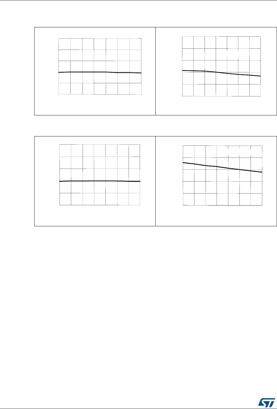
Typical characteristic
L6384E
12/18
DocID13862 Rev 3
Figure 1
1. V
CC
UV turn-on vs. t
emperature
Figure 12.
Output source
current
vs. temperature
Figure 13. V
CC
UV turn-off
vs. temperat
ure
Figure 14. Outpu
t sink current
vs. temperature
-45
-
25
0
25
50
75
100
125
10
11
12
13
14
15
Vccth1 (V)
Tj (°C)
Typ.
-45
-
25
0
25
50
75
100
125
10
11
12
13
14
15
Vccth1 (V)
Tj (°C)
Typ.
-45
-25
0
25
50
75
100
125
0
200
400
600
800
1000
Current (mA)
Tj (°C)
Typ.
@ Vcc = 14.4V
-45
-25
0
25
50
75
100
125
0
200
400
600
800
1000
Current (mA)
Tj (°C)
Typ.
@ Vcc = 14.4V
-45
-25
0
25
50
75
100
125
8
9
10
11
12
13
Vccth2 (V)
Tj (°C)
Typ.
-45
-25
0
25
50
75
100
125
8
9
10
11
12
13
Vccth2 (V)
Tj (°C)
Typ.
-45
-25
0
25
50
75
100
125
0
200
400
600
800
1000
Current (mA)
Tj (°C)
Typ.
@ Vcc = 14.4V
-45
-25
0
25
50
75
100
125
0
200
400
600
800
1000
Current (mA)
Tj (°C)
Typ.
@ Vcc = 14.4V
P1-P3
P4-P6
P7-P9
P10-P12
P13-P15
P16-P18
L6384E
Mfr. #:
Buy L6384E
Manufacturer:
STMicroelectronics
Description:
Gate Drivers HV H-Bridge drive
Lifecycle:
New from this manufacturer.
Delivery:
DHL
FedEx
Ups
TNT
EMS
Payment:
T/T
Paypal
Visa
MoneyGram
Western
Union
Products related to this Datasheet
L6384ED013TR
L6384ED
L6384E