BATTERY PROTECTION IC FOR 3-SERIAL- OR 4-SERIAL-CELL PACK
S-8254A Series
Rev.5.0_01
Seiko Instruments Inc.
20
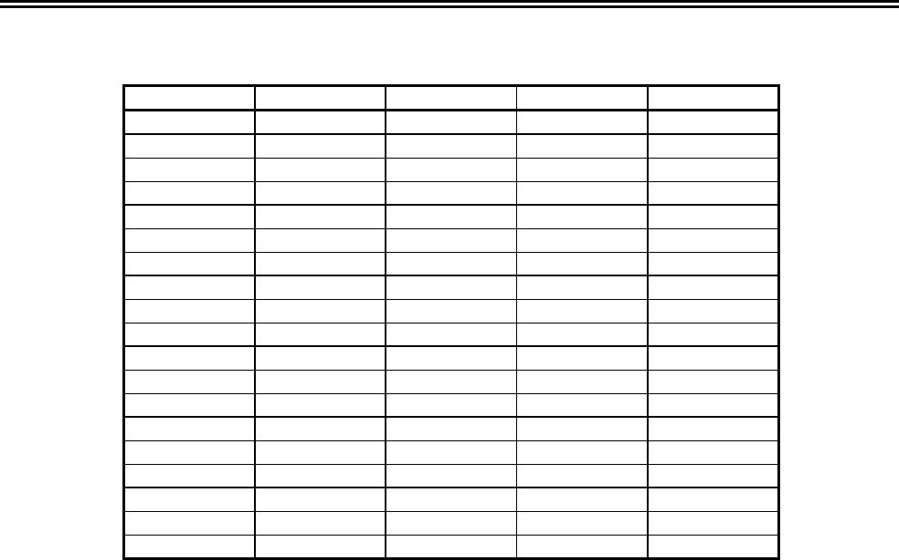
Table 7 Constants for External Components
No. Part Typical Range Unit
1 R
VC1
1 0 to 1
*1
kΩ
2 R
VC2
1 0 to 1
*1
kΩ
3 R
VC3
1 0 to 1
*1
kΩ
4 R
VC4
1 0 to 1
*1
kΩ
5 R
DOP
5.1 2 to 10
kΩ
6 R
COP
1 0.1 to 1
MΩ
7 R
VMP
5.1 1 to 10
kΩ
8 R
CTL
1 1 to 100
kΩ
9 R
VINI
1 1 to 100
kΩ
10 R
SEL
1 1 to 100
kΩ
11 R
SENSE
⎯
0 or higher
mΩ
12 R
VSS
51 10 to 51
*1
Ω
13 C
VC1
0.1 0 to 0.33
*1
μF
14 C
VC2
0.1 0 to 0.33
*1
μF
15 C
VC3
0.1 0 to 0.33
*1
μF
16 C
VC4
0.1 0 to 0.33
*1
μF
17 C
CCT
0.1 0.01 or higher
μF
18 C
CDT
0.1 0.07 or higher
μF
19 C
VSS
2.2 2.2 to 10
*1
μF
*1. Please set up a filter constant to be R
VSS
× C
VSS
≥ 51 μF • Ω and to be R
VC1
×
C
VC1
= R
VC2
× C
VC2
= R
VC3
× C
VC3
= R
VC4
× C
VC4
= R
VSS
× C
VSS
.
Caution 1. The above constants may be changed without notice.
2. It is recommended that filter constants between VDD and VSS should be set
approximately to 112 μF • Ω.
e.g. C
VSS
× R
VSS
= 2.2 μF × 51 Ω = 112 μF • Ω
Enough evaluation of transient power supply variation and overcurrent protection
function in the actual application is needed to determine the proper constants. Contact
our sales office in case the constants should be set to other than 112 μF • Ω or so.
3. It has not been confirmed whether the operation is normal or not in circuits other than
the above example of connection. In addition, the example of connection shown above
and the constant do not guarantee proper operation. Perform thorough evaluation
using the actual application to set the constant.
Precautions
• The application conditions for the input voltage, output voltage, and load current should not exceed the
package power dissipation.
• Batteries can be connected in any order, however, there may be cases when discharging cannot be
performed when a battery is connected. In this case, short the VMP pin and VDD pin or connect the
battery charger to return to the normal mode.
• When an overcharged battery and an overdischarged battery intermix, the circuit is in both the overcharge
and overdischarge statuses, so charging and discharging are not possible.
• Do not apply an electrostatic discharge to this IC that exceeds the performance ratings of the built-in
electrostatic protection circuit.
• SII claims no responsibility for any disputes arising out of or in connection with any infringement by
products including this IC of patents owned by a third party.