Design and specifications are each subject to change without notice. Ask factory for the current technical specifications before purchase and/or use.
Should a safety concern arise regarding this product, please be sure to contact us immediately.
Multilayer NTC Thermistors
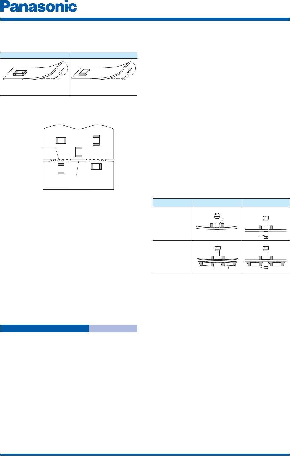
A
B
C
E
D
Slit
Magnitude of stress A>B=C>D>E
Perforation
Supporting
pin
Supporting
pin
Crack
Separation of Solder
Crack
(1) To minimize mechanical stress caused by the
warp or bending of a PC board, please follow
the recommended Thermistors’ layout below.
(2) The following layout is for your reference since
mechanical stress near the dividing/breaking
position of a PC board varies depending on
the mounting position of the Thermistors.
(3) The magnitude of mechanical stress applied to
the Thermistors when dividing the circuit board
in descending order is as follows:
push back < slit < V-groove < perforation.
Also take into account the layout of the
Thermistors and the dividing/breaking method.
(4) When the Thermistors are placed near heating
elements such as heater, etc., cracks from thermal
stresses may occur under following situation:
· Soldering the Thermistors directly to heating
elements.
· Sharing the land with heating elements.
If planning to conduct above-mentioned mounting
and/or placement, please contact us in advance.
2.5 Mounting Density and Spaces
Intervals between components should not be too
narrow to prevent the influence from solder bridges
and solder balls. The space between components
should be carefully determined.
1. Storage
(1) The Thermistors shall be stored between 5 to
40 °C and 20 to 70 % RH, not under severe
conditions of high temperature and humidity.
(2) If stored in a place where humidity, dust, or
corrosive gasses (hydrogen sulfide, sulfurous
acid, hydrogen chloride and ammonia, etc.) are
contained, the solderability of terminal electrodes
will be deteriorated.
In addition, storage in a places where the heat
or direct sunlight exposure occur will cause
mounting problems due to deformation of tapes
and reels and components and taping/reels
sticking together.
(3) Do not store components longer than 6
months. Check the solderability of products
that have been stored for more than 6 months
before use
2. Chip Mounting Consideration
(1) When mounting the Thermistors/components
on a PC board, the Thermistor bodies shall
be free from excessive impact loads such
as mechanical impact or stress due to the
positioning, pushing force and displacement of
vacuum nozzles during mounting.
(2) Maintenance and inspection of the Chip
Mounter must be performed regularly.
(3) If the bottom dead center of the vacuum
nozzle is too low, the Thermistor will crack from
excessive force during mounting.
The following precautions and recommendations
are for your reference in use.
(a)
Set and adjust the bottom dead center of the
vacuum nozzles to the upper surface of the PC
board after correcting the warp of the PC board.
(b) Set the pushing force of the vacuum nozzle
during mounting to 1 to 3 N in static load.
(c) For double surface mounting, apply a
supporting pin on the rear surface of the PC
board to suppress the bending of the PC
board in order to minimize the impact of the
vacuum nozzles. Typical examples are shown
in the table below.
Item Prohibited mounting
Recommended mounting
Single surface
mouting
The supporting pin does not necessarily
have to be positioned beneath the
Thermistor.
Double surface
mounting
(d) Adjust the vacuum nozzles so that their bottom
dead center during mounting is not too low.
(4) The closing dimensions of the positioning
chucks shall be controlled. Maintenance
and replacement of positioning chucks shall
be performed regularly to prevent chipping
or cracking of the Thermistors caused by
mechanical impact during positioning due to
worn positioning chucks.
(5) Maximum stroke of the nozzle shall be
adjusted so that the maximum bending of PC
board does not exceed 0.5 mm at 90 mm
span. The PC board shall be supported by an
adequate number of supporting pins.
3. Selection of Soldering Flux
Soldering flux may seriously affect the performance
of the Thermistors. The following shall be confirmed
before use.
(1)
The soldering flux should have a halogen based
content of 0.1 wt% (converted to chlorine) or below.
Do not use soldering flux with strong acid.
(2) When applying water-soluble soldering flux,
wash the Thermistors sufficiently because
the soldering flux residue on the surface of
PC boards may deteriorate the insulation
resistance on the Thermistors’ surface.
Prohibited layout Recommended layout
Layout the Thermistors sideways
against the stressing direction
Precautions for Assembly
May. 201503

