Design and specifications are each subject to change without notice. Ask factory for the current technical specifications before purchase and/or use.
Should a safety concern arise regarding this product, please be sure to contact us immediately.
Multilayer NTC Thermistors
Time
Gradual
cooling
5
Heating3
Peak4
Temp. rise
△T
2
Preheating1
60 sec max.60 to 120 sec
Temperature (°C)
260
220
180
140
△T
Preheating
Gradual cooling
60 to 120 sec 3 sec max.
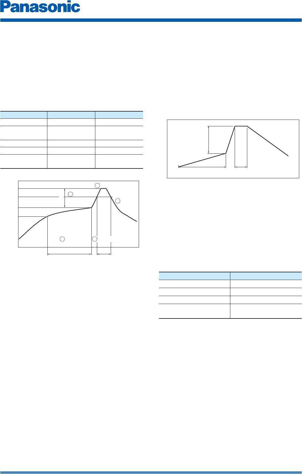
4. Soldering
4.1 Reflow Soldering
The reflow soldering temperature conditions are
composed of temperature curves of Preheating,
Temp. rise, Heating, Peak and Gradual cooling.
Large temperature difference inside the Thermistors
caused by rapid heat application to the Thermistors
may lead to excessive thermal stresses, contributing
to the thermal cracks. The Preheating temperature
requires controlling with great care so that tombstone
phenomenon may be prevented.
Item
Temperature Period or Speed
1
Preheating 140 to 180 °C 60 to 120 sec
2
Temp. rise
Preheating temp
to Peak temp.
2 to 5 °C /sec
3
Heating 220 °C min. 60 sec max.
4
Peak 260 °C max. 10 sec max.
5
Gradual cooling
Peak temp.
to 140 °C
1 to 4 °C /sec
Recommended pro le of Re ow soldering (EX)
△T : Allowable temperature difference △T
<
150 °C
The rapid cooling (forced cooling) during Gradual
cooling part should be avoided, because this may
cause defects such as the thermal cracks, etc.
When the Thermistors are immersed into a cleaning
solvent, make sure that the surface temperatures of
the devices do not exceed 100 °C.
Performing reflow soldering twice under
the conditions shown in the figure above
[Recommended profile of Reflow soldering (EX)] will
not cause any problems. However, pay attention to
the possible warp and bending of the PC board.
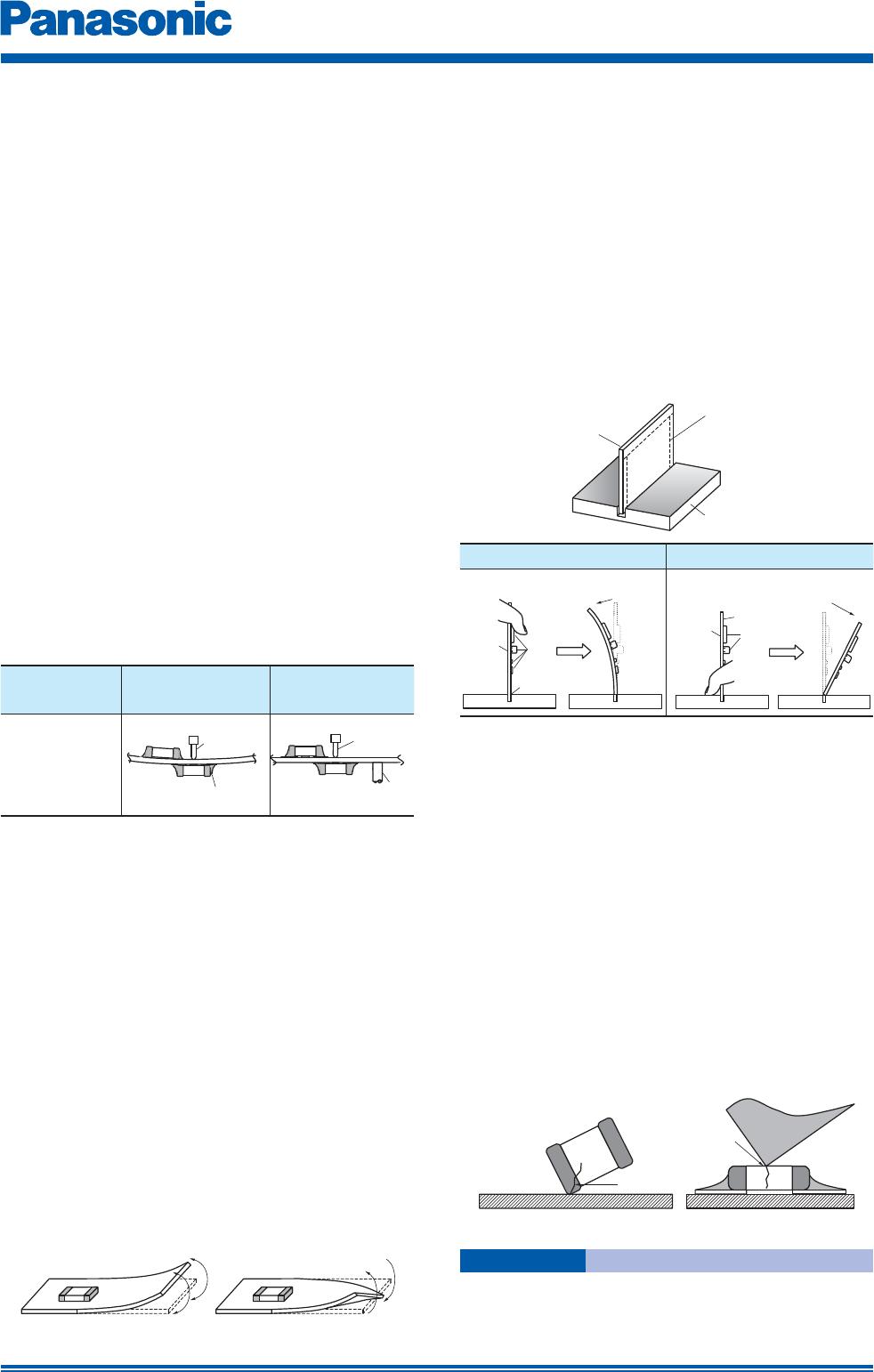
4.2 Hand Soldering
Hand soldering typically causes significant temperature
change, which may induce excessive thermal stresses
inside the Thermitors, resulting in the thermal cracks, etc.
In order to prevent any defects, the following should
be observed.
· The temperature of the soldering tips should be
controlled with special care.
· The direct contact of soldering tips with the
Thermistors and/or terminal electrodes should be
avoided.
· Dismounted Thermistors shall not be reused.
(1) Condition 1 (with preheating)
(a) Soldering:
Use thread solder (
f
1 mm or below) which
contains flux with low chlorine, developed
for precision electronic equipment.
(b) Preheating:
Conduct sufficient pre-heating, and make
sure that the temperature difference
between solder and Thermistors’ surface
is 150 °C or less.
(c) Temperature of Iron tip: 300 °C max.
(The required amount of solder shall be
melted in advance on the soldering tip.)
(d) Gradual cooling:
After soldering, the Thermistors shall be
cooled gradually at room temperature.
Recommended pro le of Hand soldering (EX)
△T : Allowable temperature difference △T
<
150 °C
(2) Condition 2 (without preheating)
Hand soldering can be performed without
preheating, by following the conditions below:
(a) Soldering iron tip shall never directly
touch the ceramic and terminal electrodes
of the Thermistors.
(b) The lands are sufficiently preheated with a
soldering iron tip before sliding the soldering
iron tip to the terminal electrodes of the
Thermistors for soldering.
Conditions of Hand soldering without preheating
Item
Condition
Temperature of Iron tip 270 °C max.
Wattage 20 W max.
Shape of Iron tip
f
3 mm max.
Soldering time with
a soldering iron
3 sec max.
5. Post Soldering Cleaning
5.1 Cleaning solvent
Soldering flux residue may remain on the PC
board if cleaned with an inappropriate solvent.
This may deteriorate the electrical characteristics
and reliability of the Thermistors.
5.2 Cleaning conditions
Inappropriate cleaning conditions such as insufficient
cleaning or excessive cleaning may impair the electrical
characteristics and reliability of the Thermistors.
(1) Insufficient cleaning can lead to:
(a) The halogen substance found in the residue
of the soldering flux may cause the metal of
terminal electrodes to corrode.
(b) The halogen substance found in the residue
of the soldering flux on the surface of the
Thermistors may change resistance values.
(c) Water-soluble soldering flux may have more
remarkable tendencies of (a) and (b) above
compared to those of rosin soldering flux.
May. 201503