Design and specifications are each subject to change without notice. Ask factory for the current technical specifications before purchase and/or use.
Should a safety concern arise regarding this product, please be sure to contact us immediately.
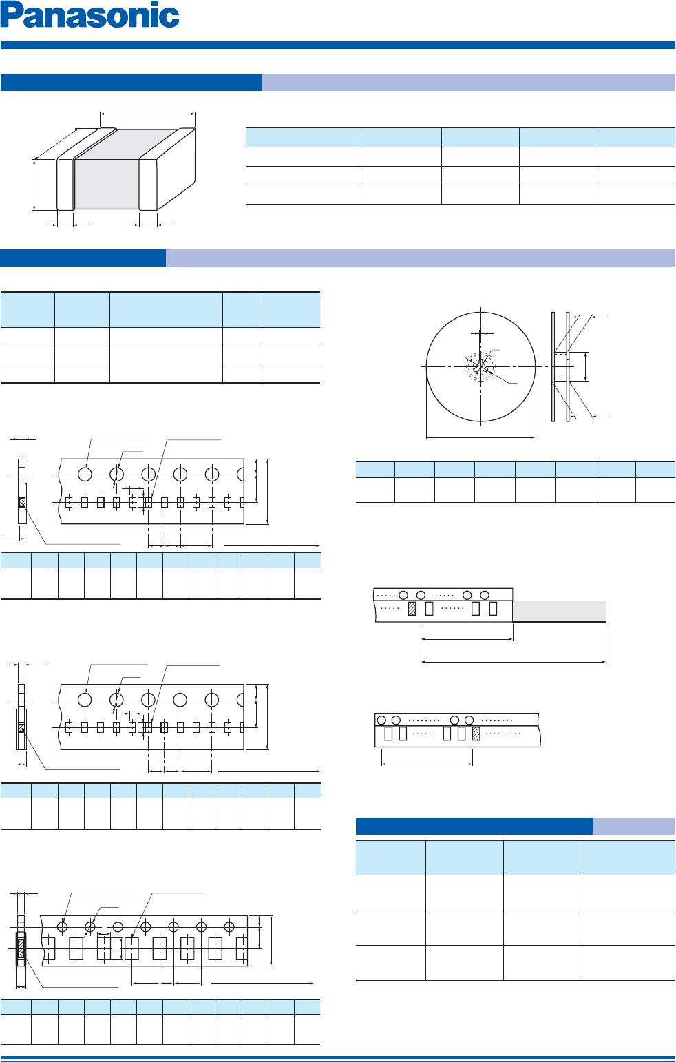
Multilayer NTC Thermistors
NTC
Rth
PMIC
ADC
Vcc
Rth
R
RL
AD
converter
CPU Interface
GMR Head
NTC
Vcc
Rth R
R
R
LCD
NTC
Item Specifi cation Test Method
Temperature
Cycling
Nallow Tol. type Standard type
R
25
change : within ±2 % within ±3 %
B Value change : within ±1 % within ±2 %
Conditions of one cycle
Step 1 : –40 °C, 30±3 min
Step 2 : Room temp., 3 min max.
Step 3 : 125 °C, 30±3 min.
Step 4 : Room temp., 3 min max.
Number of cycles: 100 cycles
Humidity Nallow Tol. type Standard type
R
25
change : within ±2 % within ±3 %
B Value change : within ±1 % within ±2 %
Temperature : 85 ±2 °C
Relative humidity : 85 ±5 %
Test period : 1000 +48/0 h
Biased Humidity Nallow Tol. type Standard type
R
25
change : within ±2 % within ±3 %
B Value change : within ±1 % within ±2 %
Temperature : 85 ±2 °C
Relative humidity : 85 ±5 %
Applied power : 10 mW(D.C.)
Test period : 500 +48/0 h
Low Temperature
Exposure
Nallow Tol. type Standard type
R
25
change : within ±2 % within ±3 %
B Value change : within ±1 % within ±2 %
Specimens are soldered on the testing board
shown in Fig.2.
Temperature : –40 ±3 °C
Test period : 1000 +48/0 h
High Temperature
Exposure
Nallow Tol. type Standard type
R
25
change : within ±2 % within ±3 %
B Value change : within ±1 % within ±2 %
Specimens are soldered on the testing board
shown in Fig.2.
Temperature : 125 ±3 °C
Test period : 1000 +48/0 h
Speci cation and Test Method
Writing current control of HDD
Contrast level control of LCD Temperature compensation of TCXO
●
Temperature Detection
●
Temperature Compensation (Pseudo-linearization)
●
Temperature Compensation (RF circuit)
Typical Application
Feb. 201704