LT3008 Series
10
3008fc
TYPICAL PERFORMANCE CHARACTERISTICS
T
A
= 25°C, unless otherwise noted.
Transient Response
500µs/DIV
V
OUT
50mV/DIV
I
OUT
20mA/DIV
3008 G31
I
OUT
= 1mA TO 20mA
V
IN
= 5.5V
V
OUT
= 5V
C
OUT
= 2.2µF
Transient Response
500µs/DIV
V
OUT
50mV/DIV
I
OUT
20mA/DIV
3008 G32
I
OUT
= 1mA TO 20mA
V
IN
= 5.5V
V
OUT
= 5V
C
OUT
= 10µF
Transient Response (Load Dump)
1ms/DIV
V
OUT
50mV/DIV
45V
12V
V
IN
10V/DIV
3008 G33
V
OUT
= 5V
I
OUT
= 20mA
C
OUT
= 4.7µF
Load Regulation Output Noise Spectral Density
FREQUENCY (Hz)
0.1
OUTPUT NOISE SPECTRAL DENSITY (µV Hz)
1
100
10
3008 G29
10 100 1k 10k 100k
5V
3.3V
2.5V
1.8V
1.5V
1V
0.6V
C
OUT
= 2.2µF
I
LOAD
= 20mA
0
0.5
2
2.5
1.5
1
3
3.5
4
4.5
5
LOAD REGULATION (mV)
3008 G28
TEMPERATURE (°C)
–50 0 75
–25
25
150
50
100
125
$I
L
= 1µA to 20mA
V
OUT
= 600mV
V
IN
= 2V
RMS Output Noise
vs Load Current
I
LOAD
(mA)
0.001
350
450
400
500
10
3008 G30
300
250
0.01 0.1 1 100
200
100
150
50
0
OUTPUT NOISE (µV
RMS
)
3.3V
2.5V
1.8V
1.2V
0.6V
1.5V
5V
C
OUT
= 10µF
LT3008 Series
11
3008fc
PIN FUNCTIONS
SHDN (Pin 1/Pin 5): Shutdown. Pulling the SHDN pin
low puts the LT3008 into a low power state and turns the
output off. If unused, tie the SHDN pin to V
IN
. The LT3008
does not function if the SHDN pin is not connected. The
SHDN pin cannot be driven below GND unless tied to the
IN pin. If the SHDN pin is driven below GND while IN is
powered, the output will turn on. SHDN pin logic cannot
be referenced to a negative rail.
GND (Pins 2, 3, 4/Pin 6): Ground. Connect the bottom
of the resistor divider that sets output voltage directly to
GND for the best regulation.
IN (Pin 5/Pin 4): Input. The IN pin supplies power to the
device. The LT3008 requires a bypass capacitor at IN if
the device is more than six inches away from the main
input fi lter capacitor. In general, the output impedance of
a battery rises with frequency, so it is advisable to include
a bypass capacitor in battery-powered circuits. A bypass
capacitor in the range of 0.1µF to 10µF will suffi ce. The
LT3008 withstands reverse voltages on the IN pin with
respect to ground and the OUT pin. In the case of a reversed
input, which occurs with a battery plugged in backwards,
the LT3008 acts as if a blocking diode is in series with its
input. No reverse current fl ows into the LT3008 and no
reverse voltage appears at the load. The device protects
both itself and the load.
OUT (Pin 6/Pins 2, 3): Output. This pin supplies power
to the load. Use a minimum output capacitor of 2.2µF
to prevent oscillations. Large load transient applications
require larger output capacitors to limit peak voltage
transients. See the Applications Information section for
more information on output capacitance and reverse-output
characteristics.
ADJ (Pin 7/Pin 1): Adjust. This pin is the error amplifi ers
inverting terminal. Its 400pA typical input bias current
ows out of the pin (see curve of ADJ Pin Bias Current vs
Temperature in the Typical Performance Characteristics
section). The ADJ pin voltage is 600mV referenced to GND
and the output voltage range is 600mV to 44.5V.
NC (Pin 8, TSOT-23 Package Only): No Connect. Pin 8
is an NC pin in the TSOT-23 package. This pin is not tied
to any internal circuitry. It may be fl oated, tied to V
IN
or
tied to GND.
GND (Exposed Pad Pin 7, DFN Package Only): Ground. The
exposed pad (backside) of the DFN package is an electrical
connection to GND. To ensure optimum performance,
solder Pin 7 to the PCB and tie directly to Pin 6.
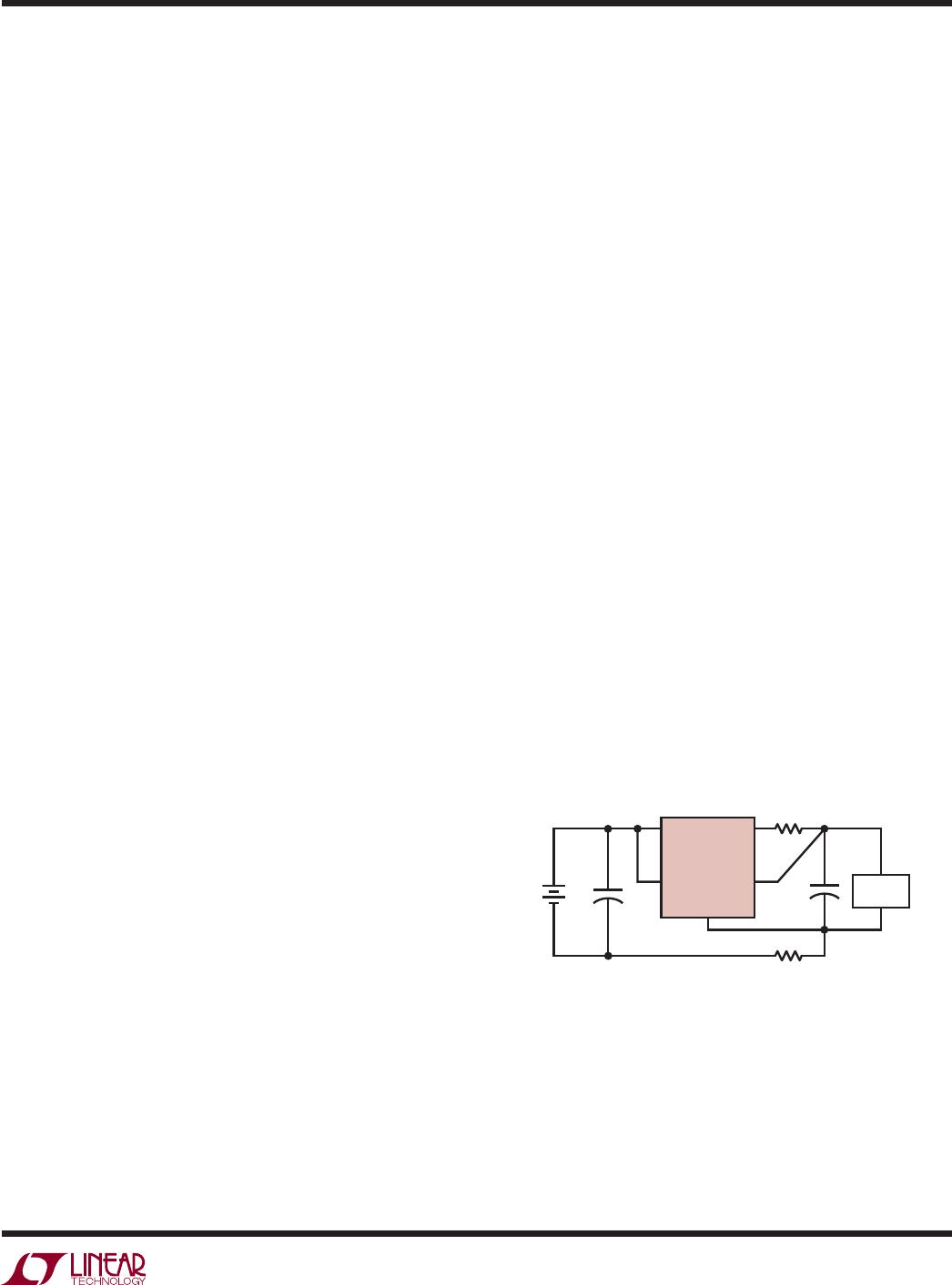
SENSE (Pin 7/Pin 1): Sense. For fi xed voltage versions of
the LT3008 (LT3008-1.2, LT3008-1.5, LT3008-1.8, LT3008-
2.5, LT3008-3.3, LT3008-5), the SENSE pin is the input to
the error amplifi er. Optimum regulation is obtained at the
point where the SENSE pin is connected to the OUT pin of
the regulator. In critical applications, small voltage drops
are caused by the resistance (RP) of PC traces between
the regulator and the load. These may be eliminated by
connecting the SENSE pin to the output at the load as
shown in Figure 1 (Kelvin Sense Connection). Note that
the voltage drop across the external PC traces add to the
dropout voltage of the regulator. The SENSE pin bias current
is 1µA at the nominal rated output voltage. The SENSE pin
can be pulled below ground (as in a dual supply system
where the regulator load is returned to a negative supply)
and still allow the device to start and operate.
(TSOT-23/DFN)
IN
SHDN
3008 F01
R
P
OUT
V
IN
SENSE
GND
LT3008
R
P
+
+
LOAD
Figure 1. Kelvin Sense Connection
LT3008 Series
12
3008fc
APPLICATIONS INFORMATION
The LT3008 is a low dropout linear regulator with ultra-
low quiescent current and shutdown. Quiescent current
is extremely low at 3µA and drops well below 1µA in
shutdown. The device supplies up to 20mA of output current.
Dropout voltage at 20mA is typically 300mV. The LT3008
incorporates several protection features, making it ideal for
use in battery-powered systems. The device protects itself
against both reverse-input and reverse-output voltages.
In battery backup applications, where a backup battery
holds up the output when the input is pulled to ground,
the LT3008 acts as if a blocking diode is in series with its
output and prevents reverse current fl ow. In applications
where the regulator load returns to a negative supply, the
output can be pulled below ground by as much as 50V
without affecting start-up or normal operation.
Adjustable Operation
The LT3008 has an output voltage range of 0.6V to 44.5V.
Figure 2 shows that output voltage is set by the ratio of two
external resistors. The IC regulates the output to maintain
the ADJ pin voltage at 600mV referenced to ground. The
current in R1 equals 600mV/R1 and the current in R2 is
the current in R1 minus the ADJ pin bias current. The ADJ
pin bias current, typically 400pA at 25°C, fl ows out of the
pin. Calculate the output voltage using the formula in Figure
2. An R1 value of 619k sets the divider current to 0.97µA.
Do not make R1’s value any greater than 619k to minimize
output voltage errors due to the ADJ pin bias current and
to insure stability under minimum load conditions. In
shutdown, the output turns off and the divider current is
zero. Curves of ADJ Pin Voltage vs Temperature and ADJ
Pin Bias Current vs Temperature appear in the Typical
Performance Characteristics.
Specifi cations for output voltages greater than 0.6V are
proportional to the ratio of the desired output voltage to
0.6V: V
OUT
/0.6V. For example, load regulation for an output
current change of 100µA to 20mA is –0.5mV typical at
V
OUT
= 0.6V. At V
OUT
= 5V, load regulation is:
5V
0.6V
•(0.5mV) =−4.17mV
Table 1 shows resistor divider values for some com-
mon output voltages with a resistor divider current of
about 1µA.
Figure 2. Adjustable Operation
Table 1. Output Voltage Resistor Divider Values
V
OUT
R1 R2
1V 604k 402k
1.2V 590k 590k
1.5V 590k 887k
1.8V 590k 1.18M
2.5V 590k 1.87M
3V 590k 2.37M
3.3V 619k 2.8M
5V 590k 4.32M
IN
SHDN
R2
R1
3008 F02
OUT
V
IN
V
OUT
= 600mV • (1 + R2/R1) – (I
ADJ
• R2)
V
ADJ
= 600mV
I
ADJ
= 0.4nA at 25°C
OUTPUT RANGE = 0.6V to 44.5V
ADJ
GND
L
T3008
V
OUT

LT3008EDC#TRMPBF

Mfr. #:
Manufacturer:
Analog Devices / Linear Technology
Description:
LDO Voltage Regulators 3uA Iq, 20mA Low Dropout Linear Regulators
Lifecycle:
New from this manufacturer.
Delivery:
DHL FedEx Ups TNT EMS
Payment:
T/T Paypal Visa MoneyGram Western Union