VS-ST303C Series
www.vishay.com
Vishay Semiconductors
Revision: 20-Dec-13
4
Document Number: 94373
For technical questions within your region: DiodesAmericas@vishay.com
, DiodesAsia@vishay.com, DiodesEurope@vishay.com
THIS DOCUMENT IS SUBJECT TO CHANGE WITHOUT NOTICE. THE PRODUCTS DESCRIBED HEREIN AND THIS DOCUMENT
ARE SUBJECT TO SPECIFIC DISCLAIMERS, SET FORTH AT www.vishay.com/doc?91000
Note
• The table above shows the increment of thermal resistance R
thJ-hs
when devices operate at different conduction angles than DC
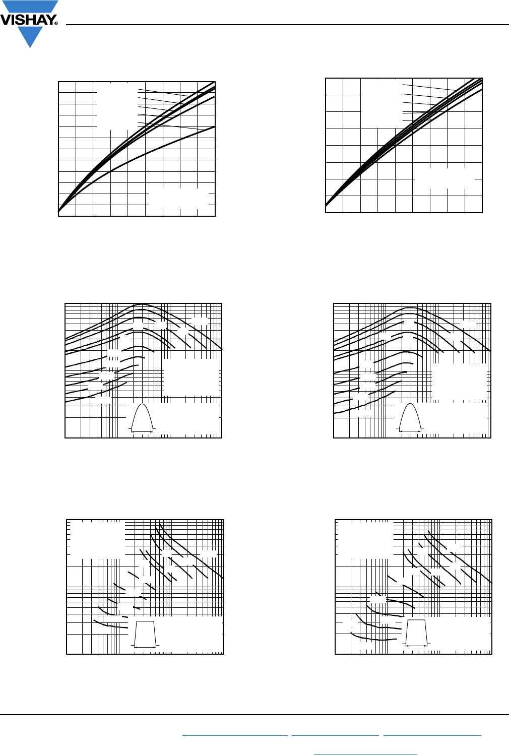
Fig. 1 - Current Ratings Characteristics
Fig. 2 - Current Ratings Characteristics
Fig. 3 - Current Ratings Characteristics
Fig. 4 - Current Ratings Characteristics
ΔR
thJ-hs
CONDUCTION
CONDUCTION ANGLE
SINUSOIDAL CONDUCTION RECTANGULAR CONDUCTION
TEST CONDITIONS UNITS
SINGLE SIDE DOUBLE SIDE SINGLE SIDE DOUBLE SIDE
180° 0.010 0.010 0.007 0.007
T
J
= T
J
max. K/W
120° 0.012 0.012 0.012 0.013
90° 0.015 0.015 0.016 0.017
60° 0.022 0.022 0.023 0.023
30° 0.036 0.036 0.036 0.037
0
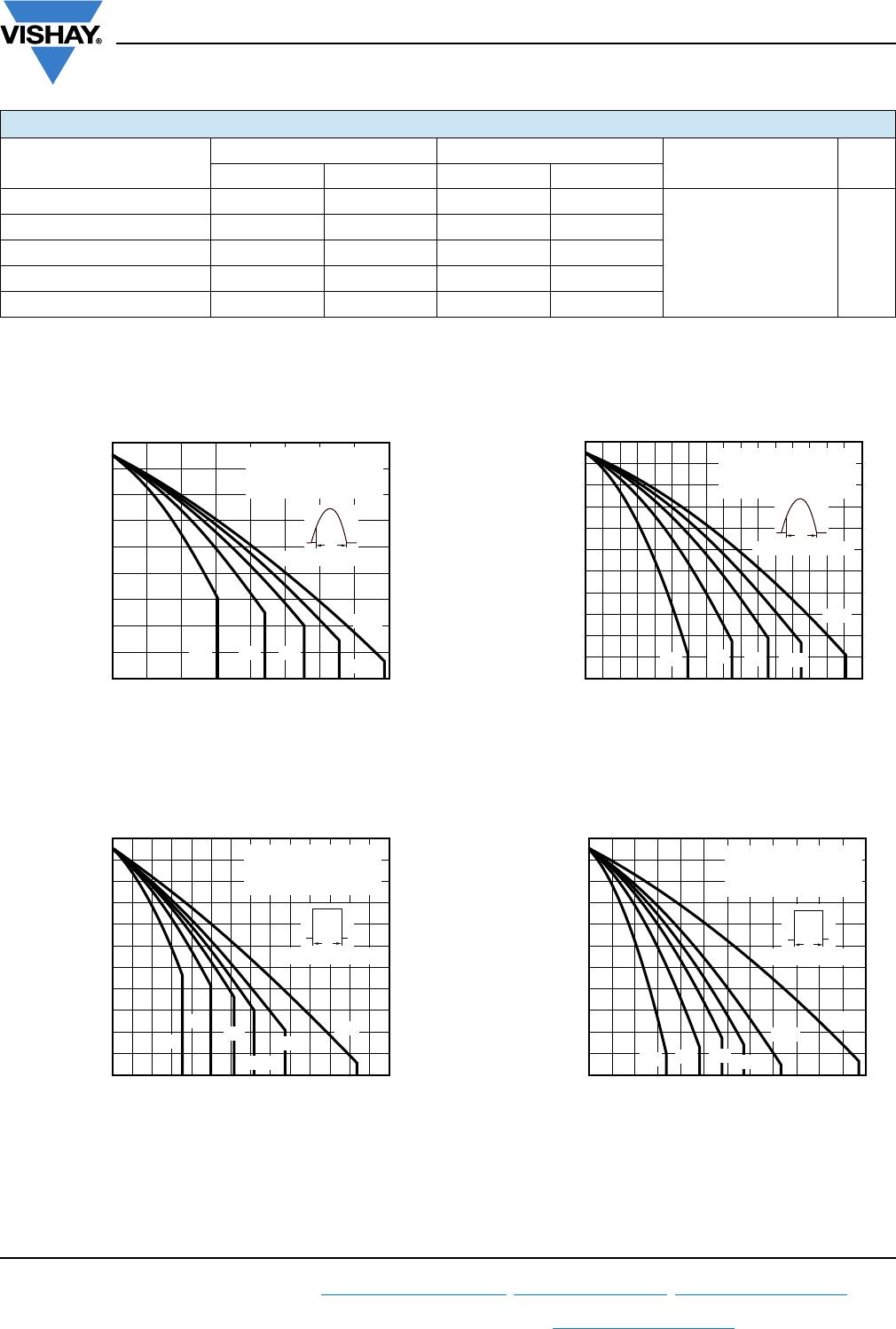
250 300 350 400
Maximum Allowable
Heatsink Temperature (°C)
Average On-State Current (A)
50
100
150 200
40
50
60
70
80
90
100
110
120
130
ST303C..C Series
(Single side cooled)
R
thJ-hs
(DC) = 0.09 K/W
Ø
Conduction angle
60°30° 90°
120°
180°
0
500 600 700
Average On-State Current (A)
100 300
200 400
Maximum Allowable
Heatsink Temperature (°C)
20
30
40
50
60
70
80
90
100
110
120
130
ST303C..C Series
(Single side cooled)
R
thJ-hs
(DC) = 0.09 K/W
Ø
Conduction period
30°
60°
90°
120°
180°
DC
0
400300 500 600 700
800
Average On-State Current (A)
100 200
Maximum Allowable
Heatsink Temperature (°C)
30
20
40
50
60
70
80
90
100
110
120
130
30°
60°
90°
180°
ST303C..C Series
(Double side cooled)
R
thJ-hs
(DC) = 0.04 K/W
Ø
Conduction angle
120°
Average On-State Current (A)
Maximum Allowable
Heatsink Temperature (°C)
0
600 800
1000
1200
200 400
20
30
40
50
60
70
80
90
100
110
120
130
ST303C..C Series
(Double side cooled)
R
thJ-hs
(DC) = 0.04 K/W
Ø
Conduction period
30°
60°
DC
180°
90°
120°