LTC4151
4
4151ff
For more information www.linear.com/LTC4151
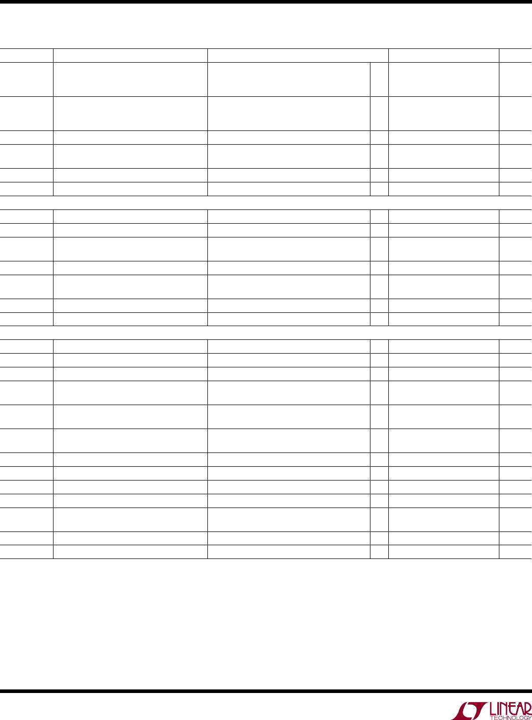
SYMBOL PARAMETER CONDITIONS MIN TYP MAX UNITS
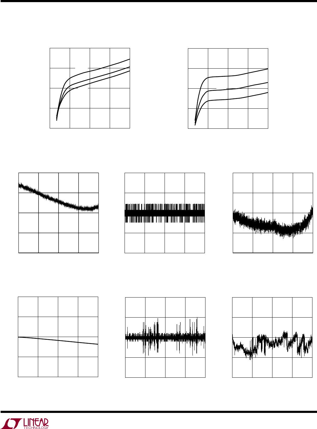
INL Integral Nonlinearity (SENSE
+
– SENSE
)
V
IN
(Note 5)
ADIN
l
l
l
±1
±1
±0.5
±3
±3
±2
LSB
LSB
LSB
s
T
Transition Noise (SENSE
+
– SENSE
)
V
IN
ADIN
1.2
0.3
22
µV
RMS
mV
RMS
µV
RMS
f
CONV
Conversion Rate (Continuous Mode)
l
6 7.5 9 Hz
t
CONV
Conversion Time (Snapshot Mode) (SENSE
+
– SENSE
)
ADIN, V
IN
l
l
53
26
67
33
85
42
ms
ms
R
ADIN
ADIN Pin Input Resistance ADIN = 3V
l
2 10
MW
I
ADIN
ADIN Pin Input Current ADIN = 3V
l
±2 µA
I
2
C Interface
V
ADR(H)
ADR0, ADR1 Input High Threshold
l
2.3 2.65 3.0 V
V
ADR(L)
ADRO, ADRI Input Low Threshold
l
0.2 0.6 0.9 V
I
ADR(IN)
ADRO, ADRI Input Current ADR0, ADR1 = 0V or 3V
ADR0, ADR1 = 0.8V or 2.2V
l
l
±8
±70 µA
µA
V
SDA(OL)
SDA, SDAO, SDAO Output Low Voltage I
SDA
, I
SDAO
, I
SDAO
= 8mA
l
0.15 0.4 V
I
SDA,SCL(IN)
SDA, SDAI, SDAO, SDAO, SCL Input
Current
SDA, SDAI, SDAO, SDAO, SCL = 5V
l
0 ±2 µA
V
SDA,SCL(TH)
SDA, SDAI, SCL Input Threshold
l
1.6 1.8 2 V
V
SDA,SCL(CL)
SDA, SDAI, SCL Clamp Voltage I
SDA
, I
SDAI
, I
SCL
= 3mA
l
5.5 6.1 6.6 V
I
2
C Interface Timing (Note 4)
f
SCL(MAX)
Maximum SCL Clock Frequency 400 kHz
t
LOW
Minimum SCL Low Period 0.65 1.3 µs
t
HIGH
Minimum SCL High Period 50 600 ns
t
BUF(MIN)
Minimum Bus Free Time Between Stop/
Start Condition
0.12 1.3 µs
t
HD,STA(MIN)
Minimum Hold Time After (Repeated) Start
Condition
140 600 ns
t
SU,STA(MIN)
Minimum Repeated Start Condition Set-Up
Time
30 600 ns
t
SU,STO(MIN)
Minimum Stop Condition Set-Up Time 30 600 ns
t
HD,DATI(MIN)
Minimum Data Hold Time Input –100 0 ns
t
HD,DATO(MIN)
Minimum Data Hold Time Output 300 600 900 ns
t
SU,DAT(MIN)
Minimum Data Set-Up Time Input 30 100 ns
t
SP(MAX)
Maximum Suppressed Spike
Pulse Width
50 110 250 ns
t
RST
Stuck-Bus Reset Time SCL or SDA/SDAI Held Low 20 33 ms
C
X
SCL, SDA Input Capacitance 5 10 pF
Note 1: Stresses beyond those listed under Absolute Maximum Ratings
may cause permanent damage to the device. Exposure to any Absolute
Maximum Rating condition for extended periods may affect device
reliability and lifetime.
Note 2: Internal clamps limit the SCL, SDA (LTC4151) and SDAI
(LTC4151-1/LTC4151-2) pins to a minimum of 5.5V. Driving these pins to
voltages beyond the clamp may damage the part. The pins can be safely
tied to higher voltages through a resistor that limits the current below
5mA.
elecTrical characTerisTics
The l denotes the specifications which apply over the full operating
temperature range, otherwise specifications are at T
A
= 25°C. V
IN
is from 7V to 80V, unless noted. (Note 3)
Note 3: All currents into pins are positive. All voltages are referenced to
GND, unless otherwise noted.
Note 4: Guaranteed by design and not subject to test.
Note 5: Integral nonlinearity and total unadjusted error of V
IN
are tested
between 7V and 80V.
Note 6: Offset error of V
IN
is defined by extrapolating the straight line
measured between 7V and 80V.
LTC4151
5
4151ff
For more information www.linear.com/LTC4151
CODE
0
ADC DNL (LSB)
0
0.5
4096
–0.5
–1.0
1024
2048
3072
1.0
4151 G04
CODE
0
0
0.5
4096
–0.5
–1.0
1024
2048
3072
1.0
4151 G05
Typical perForMance characTerisTics
Supply Current vs Supply Voltage
(Normal Mode)
Supply Current vs Supply Voltage
(Shutdown Mode)
ADC Total Unadjusted Error
vs Code (ADIN Voltage)
ADC INL vs Code (ADIN Voltage)
V
IN
= 12V, T
A
= 25°C, unless noted.
ADC DNL vs Code (ADIN Voltage)
SUPPLY VOLTAGE (V)
0
SUPPLY CURRENT (mA)
1.00
1.15
80
0.85
0.70
20
40
60
1.30
4151 G01
40°C
85°C
25°C
SUPPLY VOLTAGE (V)
0
SUPPLY CURRENT (µA)
200
300
80
100
0
20
40
60
400
4151 G02
40°C
85°C
25°C
CODE
0
ADC TOTAL UNADJUSTED ERROR (%)
0
0.05
4096
–0.05
–0.10
1024
2048
3072
0.10
4151 G03
ADC Total Unadjusted Error
vs Code (SENSE Voltage)
ADC DNL vs Code (SENSE Voltage)
ADC INL vs Code (SENSE Voltage)
CODE
0
ADC INL (LSB)
0
1
4096
–1
–2
1024
2048
3072
2
4151 G08
CODE
0
ADC TOTAL UNADJUSTED ERROR (%)
0
0.5
4096
–0.5
–1.0
1024
2048
3072
1.0
4151 G06
CODE
0
ADC DNL (LSB)
0
1
4096
–1
–2
1024
2048
3072
2
4151 G07
LTC4151
6
4151ff
For more information www.linear.com/LTC4151
pin FuncTions
ADIN: ADC Input. The onboard ADC measures voltage
range between 0V and 2.048V. Tie to GND if unused.
ADR1, ADR0: I
2
C Device Address Inputs. Connecting
ADR1 and ADR0 to V
IN
, GND or leaving the pins open
configures one of nine possible addresses. See Table 1
in the Applications Information section for details.
Exposed
Pad (DD Package Only): Exposed pad may be
left open or connected to device ground (GND).
GND: Device Ground.
SCL: I
2
C Bus Clock Input. Data is shifted in and out at
the SDA pin on rising edges of SCL. This pin is driven
by an open-collector output from a master controller. An
external pull-up resistor or current source is required and
can be placed between SCL and V
IN
. The voltage at SCL
is internally clamped to 6V (5.5V minimum).
SDA (LTC4151 Only): I
2
C Bus Data Input/Output. Used
for shifting in address, command or data bits and sending
out data. An external pull-up resistor or current source
is required and can be placed between SDA and V
IN
.
The voltage at SDA is internally clamped to 6V (5.5V
minimum).
SDAI
(LTC4151-1/LTC4151-2 Only): I
2
C Bus Data Input.
Used for shifting in address, command, data, and SDAO
acknowledge bits. This pin is driven by an open-collector
output from a master controller. An external pull-up resistor
or current source is required and can be placed between
SDAI and V
IN
. If the master separates SDAI and SDAO,
data read at SDAO needs to be echoed back to SDAI for
proper I
2
C communication. The voltage at SDAI is internally
clamped to 6V (5.5V minimum).
SDAO (LTC4151-2 Only): Serial Bus Data Output. Open-
drain output used for sending data back to the master
controller or acknowledging a write operation. Normally
tied to SDAI to form the SDA line. An external pull-up
resistor or current source is required.
SDAO (LTC4151-1 Only): Inverted Serial Bus Data Out
-
put. Open
-drain output used for sending data back to the
master
controller or acknowledging a write operation. Data
is inverted for convenience of opto-isolation. An external
pull-up resistor or current source is required.
SENSE
+
: Kelvin Sense of the V
IN
Pin. See Figure 10 for
recommended Kelvin connection.
SENSE
: High Side Current Sense Input. Connect an
external sense resistor between SENSE
+
and SENSE
.
The differential voltage between SENSE
+
and SENSE
is
monitored by the onboard ADC with a full-scale sense
voltage of 81.92mV.
Typical perForMance characTerisTics
V
IN
= 12V, T
A
= 25°C, unless noted.
SDA, SDAO, SDAO Output Low vs
Pull-Up Current (V
SDA(OL)
vs I
SDA
)
SDA, SDAI, SCL Clamp Voltage
vs Load Current
I
SDA
(mA)
0
V
SDA(OL)
(V)
0.3
0.4
20
0.2
0.1
0
5
10
15
0.5
4151 G09
40°C
25°C
85°C
I
LOAD
(mA)
0.01 0.1 1 10
6.2
6.1
6.0
5.9
6.3
4151 G10
V
SDA,SCL(CL)
(V)
40°C
85°C
25°C

LTC4151CS-2#TRPBF

Mfr. #:
Manufacturer:
Analog Devices Inc.
Description:
Current & Power Monitors & Regulators 80V HIgh-Side Power Monitor with Shutdown
Lifecycle:
New from this manufacturer.
Delivery:
DHL FedEx Ups TNT EMS
Payment:
T/T Paypal Visa MoneyGram Western Union