MAX4885
Complete VGA 1:2 or 2:1 Multiplexer
_______________________________________________________________________________________ 9
Detailed Description
The MAX4885 integrates high-bandwidth analog
switches and level-translating buffers to implement a
complete 1:2 or 2:1 multiplexer for VGA signals. The
device provides switching for RGB, HSYNC, VSYNC,
and DDC signals. A low-noise charge pump with inter-
nal capacitors provides a boosted gate-drive voltage to
improve performance of the RGB switches.
The device provides two modes of operation: 1:2 and
2:1. In 1:2 mode (M = 0), the HSYNC and VSYNC
inputs feature level-shifting buffers to support TTL out-
put logic levels from low-voltage graphics controllers.
These buffered switches may be driven from as little as
+2.0V up to +5.5V. In 2:1 mode (M=1), the output
buffers for the HSYNC and VSYNC signals are dis-
abled. In both modes, RGB signals are routed with the
same high-performance analog switches, and DDC sig-
nals are voltage clamped to a diode drop less than
V
CL
. Voltage clamping provides protection and com-
patibility with DDC signals and low-voltage ASICs. In
keyboard/video/mouse (KVM) applications, V
CL
is nor-
mally set to +5V because low-voltage clamping is not
required, as specified by the VESA standard.
Drive EN logic high to shut down the MAX4885. In shut-
down mode, supply current is reduced to 5µA and all
switches are high impedance, providing high-signal
rejection. The RGB, HSYNC, VSYNC, and DDC switches
are ESD protected to ±8kV by the Human Body Model.
RGB Switches
The MAX4885 provides three SPDT high-bandwidth
switches to route standard VGA R, G, and B signals
(see Table 1). A boosted gate-drive voltage is generat-
ed by an internal charge pump to improve performance
of the RGB switches. The R, G, and B analog switches
are identical, and any of the three switches can be
used to route red, green, or blue video signals. The
RGB switches function with reduced performance with
the charge pump disabled.
Charge Pump
A low-noise charge pump with internal capacitors pro-
vides a doubled voltage for driving the RGB analog
switches. Noise voltage from the charge pump is less
than 50µV
P-P.
The noise level is more than 80dB below
the signal level, making the charge pump suitable for
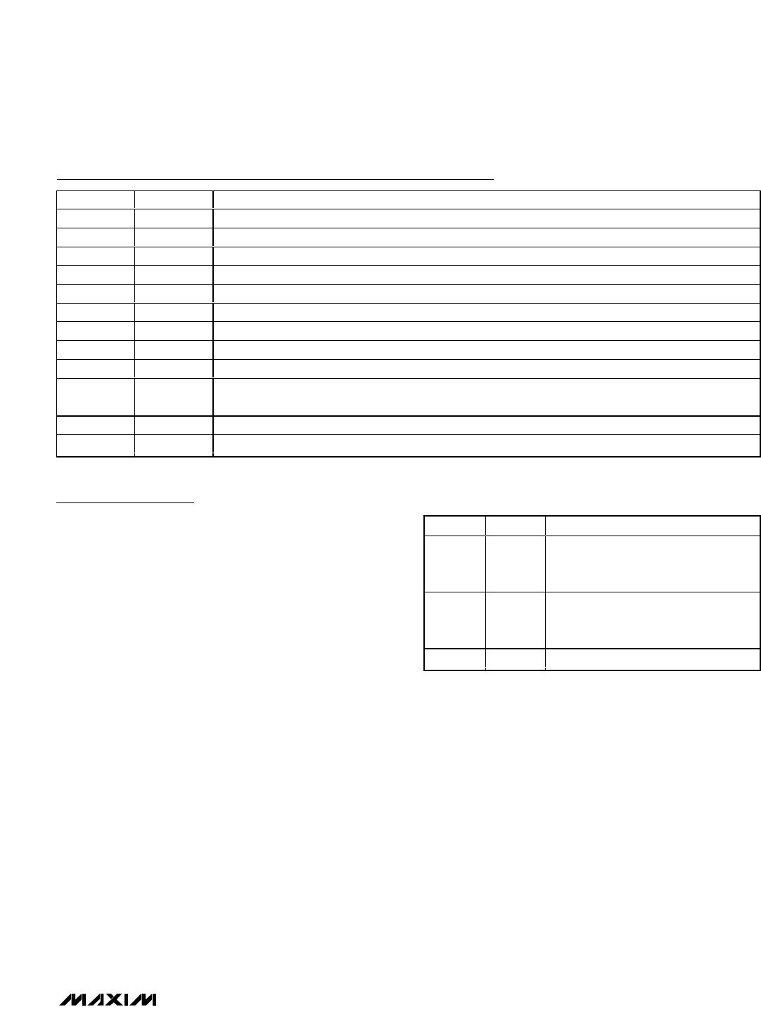
Pin Description (continued)