IL300-EF-X007T

IL300
www.vishay.com
Vishay Semiconductors
Rev. 1.8, 02-Jun-14
7
Document Number: 83622
For technical questions, contact: optocoupleranswers@vishay.com
THIS DOCUMENT IS SUBJECT TO CHANGE WITHOUT NOTICE. THE PRODUCTS DESCRIBED HEREIN AND THIS DOCUMENT
ARE SUBJECT TO SPECIFIC DISCLAIMERS, SET FORTH AT www.vishay.com/doc?91000
Fig. 11 - Isolated Control Amplifier
For best input offset compensation at U1, R2 will equal R3.
The value of R1 can easily be calculated from the following.
The value of R5 depends upon the IL300 Transfer Gain (K3).
K3 is targeted to be a unit gain device, however to minimize
the part to part Transfer Gain variation, Infineon offers K3
graded into ± 5 % bins. R5 can determined using the
following equation,
or if a unity gain amplifier is being designed
(V
MONITOR
= V
OUT
, R1 = 0), the equation simplifies to:
Fig. 12 - Switching Mode Power Supply
Fig. 13 - DC Coupled Power Supply Feedback Amplifier
iil300_16
+
-
Voltage
monitor
R1
R2
To control
input
ISO
AMP
+1
R1 R2 x
V
MONITOR
V
a
-------------------------
- 1


=
R5
V
OUT
V
MONITOR
---------------------------
x
R3 x R1 R2+
R2 x K3
-----------------------------------------
=
R5
R3
K3
-------
=
iil300_17
Switch
Xformer
Switch
mode
regulator
TDA4918
Isolated
feedback
Control
110/
220
main
DC output
AC/DC
rectifier
AC/DC
rectifier
iil300_18
8
7
6
5
100 pF
4
3
1
2
8
6
7
K1
V
CC
V
CC
1
2
3
4
K2
V
CC
V
monitor
R1
20 kΩ
R2
30 kΩ
R3
30 kΩ
R4
100 Ω
V
out
To
control
input
R5
30 kΩ
IL300
Vb
Va
+
-
U1
LM201
IL300
www.vishay.com
Vishay Semiconductors
Rev. 1.8, 02-Jun-14
8
Document Number: 83622
For technical questions, contact: optocoupleranswers@vishay.com
THIS DOCUMENT IS SUBJECT TO CHANGE WITHOUT NOTICE. THE PRODUCTS DESCRIBED HEREIN AND THIS DOCUMENT
ARE SUBJECT TO SPECIFIC DISCLAIMERS, SET FORTH AT www.vishay.com/doc?91000
Table 1. Gives the value of R5 given the production K3 bin.
The last step in the design is selecting the LED current
limiting resistor (R4). The output of the operational amplifier
is targeted to be 50 % of the V
CC
, or 2.5 V. With an LED
quiescent current of 12 mA the typical LED (V
F
) is 1.3 V.
Given this and the operational output voltage, R4 can be
calculated.
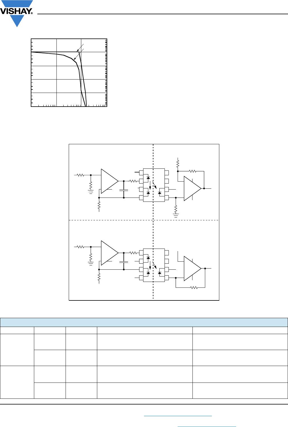
The circuit was constructed with an LM201 differential
operational amplifier using the resistors selected. The
amplifier was compensated with a 100 pF capacitor
connected between pins 1 and 8.
The DC transfer characteristics are shown in figure 17. The
amplifier was designed to have a gain of 0.6 and was
measured to be 0.6036. Greater accuracy can be achieved
by adding a balancing circuit, and potentiometer in the input
divider, or at R5. The circuit shows exceptionally good gain
linearity with an RMS error of only 0.0133 % over the input
voltage range of 4 V to 6 V in a servo mode; see figure 15.
Fig. 14 - Transfer Gain
Fig. 15 - Linearity Error vs. Input Voltage
The AC characteristics are also quite impressive offering a
-3 dB bandwidth of 100 kHz, with a -45° phase shift at
80 kHz as shown in figure 16.
TABLE 1 - R5 SELECTION
BIN
K3 R5 RESISTOR
MIN. MAX. TYP. 1 % k
A 0.560 0.623 0.59 51.1
B 0.623 0.693 0.66 45.3
C 0.693 0.769 0.73 41.2
D 0.769 0.855 0.81 37.4
E 0.855 0.950 0.93 32.4
F 0.950 1.056 1 30
G 1.056 1.175 1.11 27
H 1.175 1.304 1.24 24
I 1.304 1.449 1.37 22
J 1.449 1.610 1.53 19.4
R4
V
opamp
- V
F
I
Fq
---------------------------------
2.5 V - 1.3 V
12 mA
---------------------------------
100 ===
iil300_19
6.05.55.04.54.0
2.25
2.50
2.75
3.00
3.25
3.50
3.75
V
out
- Output Voltage (V)
V
out
= 14.4 mV + 0.6036 x V
in
LM 201 T
a
= 25 °C
iil300_20
6.05.55.04.54.0
- 0.015
- 0.010
- 0.005
0.000
0.005
0.010
0.015
0.020
0.025
V
in
- Input Voltage (V)
Linearity Error (%)
LM201
IL300
www.vishay.com
Vishay Semiconductors
Rev. 1.8, 02-Jun-14
9
Document Number: 83622
For technical questions, contact: optocoupleranswers@vishay.com
THIS DOCUMENT IS SUBJECT TO CHANGE WITHOUT NOTICE. THE PRODUCTS DESCRIBED HEREIN AND THIS DOCUMENT
ARE SUBJECT TO SPECIFIC DISCLAIMERS, SET FORTH AT www.vishay.com/doc?91000
Fig. 16 - Amplitude and Phase Power Supply Control
The same procedure can be used to design isolation
amplifiers that accept bipolar signals referenced to ground.
These amplifiers circuit configurations are shown in
figure 17. In order for the amplifier to respond to a signal that
swings above and below ground, the LED must be pre
biased from a separate source by using a voltage reference
source (V
ref1
). In these designs, R3 can be determined by the
following equation.
Fig. 17 - Non-inverting and Inverting Amplifiers
iil300_21
dB
Phase
Phase Response (°)
10
3
10
4
10
5
10
6
2
0
- 2
- 4
- 6
- 8
45
0
- 45
- 90
- 135
- 180
F - Frequency (Hz)
Amplitude Response (dB)
R3
V
ref1
I
P1
-----------
V
ref1
K1I
Fq
---------------
==
TABLE 2 - OPTOLINEAR AMPLIEFIERS
AMPLIFIER INPUT OUTPUT GAIN OFFSET
Non-inverting
Inverting Inverting
Non-inverting Non-inverting
Inverting
Inverting Non-inverting
Non-inverting Inverting
iil300_22
Vcc
20 pF
4
1
2
3
4
8
7
6
5
+ V
ref2
R5
R6
7
2
4
3
Vo
R4
R3
- V
ref1
V
in
R1
R2
3
7
6
+
+V
cc
100 Ω
6
IL 300
2
- V
cc
- V
cc
Vcc
- V
cc
+
V
cc
20 pF
4
1
2
3
4
8
7
6
5
+ V
ref2
7
2
4
3
V
out
R4
R3
+ V
ref1
V
in
R1
R2
3
7
6
+
+ V
cc
100 Ω
6
2
V
cc
V
cc
- V
cc
+
Vcc
Non-inverting input Non-inverting output
Inverting input
Inverting output
IL 300
- V
cc
V
cc
V
OUT
V
IN
-------------
K3 x R4 x R2
R3 x R1 x R2
------------------------------------------
=
V
ref2
V
ref1
x R4 x K3
R3
------------------------------------------
=
V
OUT
V
IN
-------------
K3 x R4 x R2 x R5 + R6
R3 x R5 x R1 x R2
-------------------------------------------------------------------------
=
V
ref2
- V
ref1
x R4 x R5 + R6 x K3
R3 x R6
----------------------------------------------------------------------------------
=
V
OUT
V
IN
-------------
- K3 x R4 x R2 x R5 + R6
R3 x R1 x R2
------------------------------------------------------------------------------
=
V
ref2
V
ref1
x R4 x R5 + R6 x K3
R3 x R6
------------------------------------------------------------------------------
=
V
OUT
V
IN
-------------
- K3 x R4 x R2
R3 x R1 x R2
------------------------------------------
=
V
ref2
- V
ref1
x R4 x K3
R3
----------------------------------------------
=

IL300-EF-X007T

Mfr. #:
Manufacturer:
Vishay Semiconductors
Description:
High Linearity Optocouplers Single Linear, High Gain, Wide Bandwidth
Lifecycle:
New from this manufacturer.
Delivery:
DHL FedEx Ups TNT EMS
Payment:
T/T Paypal Visa MoneyGram Western Union