AD8601/AD8602/AD8604
Rev. G | Page 16 of 24
INPUT OVERVOLTAGE PROTECTION
As with any semiconductor device, if a condition could exist
that could cause the input voltage to exceed the power supply,
the devices input overvoltage characteristic must be considered.
Excess input voltage energizes the internal PN junctions in the
AD860x, allowing current to flow from the input to the supplies.
This input current does not damage the amplifier, provided it is
limited to 5 mA or less. This can be ensured by placing a resistor in
series with the input. For example, if the input voltage could
exceed the supply by 5 V, the series resistor should be at least
(5 V/5 mA) = 1 kΩ. With the input voltage within the supply
rails, a minimal amount of current is drawn into the inputs,
which, in turn, causes a negligible voltage drop across the series
resistor. Therefore, adding the series resistor does not adversely
affect circuit performance.
OVERDRIVE RECOVERY
Overdrive recovery is defined as the time it takes the output of
an amplifier to come off the supply rail when recovering from
an overload signal. This is tested by placing the amplifier in a
closed-loop gain of 10 with an input square wave of 2 V p-p
while the amplifier is powered from either 5 V or 3 V.
The AD860x has excellent recovery time from overload conditions.
The output recovers from the positive supply rail within 200 ns
at all supply voltages. Recovery from the negative rail is within
500 ns at a 5 V supply, decreasing to within 350 ns when the
device is powered from 2.7 V.
POWER-ON TIME
The power-on time is important in portable applications where
the supply voltage to the amplifier may be toggled to shut down
the device to improve battery life. Fast power-up behavior ensures
that the output of the amplifier quickly settles to its final voltage,
improving the power-up speed of the entire system. When the
supply voltage reaches a minimum of 2.5 V, the AD860x settles to
a valid output within 1 µs. This turn-on response time is faster
than many other precision amplifiers, which can take tens or
hundreds of microseconds for their outputs to settle.
USING THE AD8602 IN HIGH SOURCE IMPEDANCE
APPLICATIONS
The CMOS rail-to-rail input structure of the AD860x allows
these amplifiers to have very low input bias currents, typically
0.2 pA. This allows the AD860x to be used in any application
that has a high source impedance or must use large value
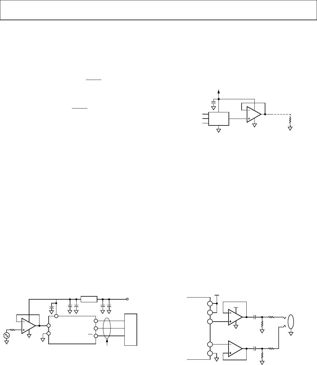
resistances around the amplifier. For example, the photodiode
amplifier circuit shown in Figure 56 requires a low input bias
current op amp to reduce output voltage error. The AD8601
minimizes offset errors due to its low input bias current and low
offset voltage.
The current through the photodiode is proportional to the incident
light power on its surface. The 4.7 MΩ resistor converts this current
into a voltage, with the output of the AD8601 increasing at 4.7 V/µA.
The feedback capacitor reduces excess noise at higher frequencies
by limiting the bandwidth of the circuit to
()
F
Cπ
BW
M7.42
1
= (1)
Using a 10 pF feedback capacitor limits the bandwidth to
approximately 3.3 kHz.
AD8601
10p
F
(OPTIONAL)
V
OUT
4.7VA
4.7M
D1
01525-056
Figure 56. Amplifier Photodiode Circuit
HIGH SIDE AND LOW SIDE, PRECISION CURRENT
MONITORING
Because of its low input bias current and low offset voltage, the
AD860x can be used for precision current monitoring. The true
rail-to-rail input feature of the AD860x allows the amplifier to
monitor current on either the high side or the low side. Using both
amplifiers in an AD8602 provides a simple method for monitoring
both current supply and return paths for load or fault detection.
Figure 57 and Figure 58 demonstrate both circuits.
01525-057
1/2 AD8602
RETURN TO
GROUND
R
SENSE
0.1
R1
100
R2
249k
Q1
2N3904
MONITOR
OUTPUT
3
V
3V
Figure 57. Low-Side Current Monitor
01525-058
3V
I
L
V+
3V
MONITOR
OUTPUT
R1
100
R2
2.49k
R
SENSE
0.1
Q1
2N3905
1/2 AD8602
Figure 58. High-Side Current Monitor
AD8601/AD8602/AD8604
Rev. G | Page 17 of 24
Voltage drop is created across the 0.1 Ω resistor that is
proportional to the load current. This voltage appears at the
inverting input of the amplifier due to the feedback correction
around the op amp. This creates a current through R1, which
in turn, pulls current through R2. For the low side monitor, the
monitor output voltage is given by
×
×=
L
SENSE
I
R1
R
R2VOutputMonitor 3 (2)
For the high side monitor, the monitor output voltage is
L
SENSE
I
R1
R
R2OutputMonitor ×
×=
(3)
Using the components shown, the monitor output transfer
function is 2.5 V/A.
USING THE AD8601 IN SINGLE-SUPPLY, MIXED
SIGNAL APPLICATIONS
Single-supply, mixed signal applications requiring 10 or more
bits of resolution demand both a minimum of distortion and a
maximum range of voltage swing to optimize performance. To
ensure that the ADCs or DACs achieve their best performance, an
amplifier often must be used for buffering or signal conditioning.
The 750 µV maximum offset voltage of the AD8601 allows the
amplifier to be used in 12-bit applications powered from a 3 V
single supply, and its rail-to-rail input and output ensure no
signal clipping.
Figure 59 shows the AD8601 used as an input buffer amplifier
to the AD7476, a 12-bit, 1 MSPS ADC. As with most ADCs,
total harmonic distortion (THD) increases with higher source
impedances. By using the AD8601 in a buffer configuration, the
low output impedance of the amplifier minimizes THD while
the high input impedance and low bias current of the op amp
minimizes errors due to source impedance. The 8 MHz gain
bandwidth product of the AD8601 ensures no signal attenua-
tion up to 500 kHz, which is the maximum Nyquist frequency
for the AD7476.
V
DD
GND
SCLK
SDATA
V
IN
CS
AD7476/AD7477
R
S
AD8601
4
3
2
5
1
1µF
TANT
SERIAL
INTERFACE
5V
SUPPLY
0.1µF 0.1µF10µF
680nF
REF193
µC/µP
01525-059
Figure 59. A Complete 3 V 12-Bit 1 MHz Analog-to-Digital Conversion System
Figure 60 demonstrates how the AD8601 can be used as an
output buffer for the DAC for driving heavy resistive loads. The
AD5320 is a 12-bit DAC that can be used with clock frequencies
up to 30 MHz and signal frequencies up to 930 kHz. The rail-
to-rail output of the AD8601 allows it to swing within 100 mV
of the positive supply rail while sourcing 1 mA of current. The
total current drawn from the circuit is less than 1 mA, or 3 mW
from a 3 V single supply.
AD8601
4
3
2
5
1
1
01525-060
V
OUT
0V TO 3V
3-WIRE
SERIAL
INTERFACE
R
L
AD5320
4
5
6
3
V
1µF
Figure 60. Using the AD8601 as a DAC Output Buffer to Drive Heavy Loads
The AD8601, AD7476, and AD5320 are all available in space-
saving SOT-23 packages.
PC100 COMPLIANCE FOR COMPUTER AUDIO
APPLICATIONS
Because of its low distortion and rail-to-rail input and output,
the AD860x is an excellent choice for low cost, single-supply
audio applications, ranging from microphone amplification
to line output buffering. Figure 38 shows the total harmonic
distortion plus noise (THD + N) figures for the AD860x. In
unity gain, the amplifier has a typical THD + N of 0.004%, or
−86 dB, even with a load resistance of 600 Ω. This is compliant
with the PC100 specification requirements for audio in both
portable and desktop computers.
Figure 61 shows how an AD8602 can be interfaced with an AC’97
codec to drive the line output. Here, the AD8602 is used as a
unity-gain buffer from the left and right outputs of the AC’97
codec. The 100 µF output coupling capacitors block dc current
and the 20 Ω series resistors protect the amplifier from short
circuits at the jack.
NOTES
1. ADDITIONAL PINS OMITTED FOR CLARITY.
01525-061
2
3
4
8
1
V
DD
V
SS
V
DD
LEFT
OUT
RIGHT
OUT
5V
5
V
AD1881
(AC’97)
A
R4
20
C1
100µF
R2
2k
+
5
6
7
R5
20
C2
100µF
R3
2k
+
B
35
29
26
36
25
AD8602
AD8602
Figure 61. A PC100-Compliant Line Output Amplifier
AD8601/AD8602/AD8604
Rev. G | Page 18 of 24
SPICE MODEL
The SPICE macro-model for the AD860x amplifier can be down-
loaded at www.analog.com. The model accurately simulates a
number of both dc and ac parameters, including open-loop gain,
bandwidth, phase margin, input voltage range, output voltage
swing vs. output current, slew rate, input voltage noise, CMRR,
PSRR, and supply current vs. supply voltage. The model is
optimized for performance at 2C. Although it functions at
different temperatures, it may lose accuracy with respect to the
actual behavior of the AD860x.

AD8601ARTZ-REEL7

Mfr. #:
Manufacturer:
Analog Devices Inc.
Description:
Precision Amplifiers RRIO SGL w/ Low Offset VTG
Lifecycle:
New from this manufacturer.
Delivery:
DHL FedEx Ups TNT EMS
Payment:
T/T Paypal Visa MoneyGram Western Union