Clock operation M41ST85W
22/43 Doc ID 7531 Rev 11
Figure 13. Crystal accuracy across temperature
Figure 14. Calibration waveform
AI07888
–160
0 10203040506070
Frequency (ppm)
Temperature °C
80–10–20–30–40
–100
–120
–140
–40
–60
–80
20
0
–20
= –0.036 ppm/°C
2
± 0.006 ppm/°C
2
K
ΔF
= K x (T – T
O
)
2
F
T
O
= 25°C ± 5°C
AI00594B
NORMAL
POSITIVE
CALIBRATION
NEGATIVE
CALIBRATION
M41ST85W Clock operation
Doc ID 7531 Rev 11 23/43
3.4 Setting alarm clock registers
Address locations 0Ah-0Eh contain the alarm settings. The alarm can be configured to go
off at a prescribed time on a specific month, date, hour, minute, or second, or repeat every
year, month, day, hour, minute, or second. It can also be programmed to go off while the
M41ST85W is in the battery backup to serve as a system wake-up call.
Bits RPT5–RPT1 put the alarm in the repeat mode of operation. Tabl e 3 shows the possible
configurations. Codes not listed in the table default to the once per second mode to quickly
alert the user of an incorrect alarm setting.
When the clock information matches the alarm clock settings based on the match criteria
defined by RPT5–RPT1, the AF (alarm flag) is set. If AFE (alarm flag enable) is also set, the
alarm condition activates the IRQ
/FT/OUT pin as shown in Figure 15. To disable alarm,
write '0' to the alarm date register and to RPT5–RPT1.
Note: If the address pointer is allowed to increment to the flag register address, an alarm condition
will not cause the interrupt/flag to occur until the address pointer is moved to a different
address. It should also be noted that if the last address written is the “Alarm Seconds,” the
address pointer will increment to the flag address, causing this situation to occur.
The IRQ
/FT/OUT output is cleared by a READ to the flags register. A subsequent READ of
the flags register is necessary to see that the value of the alarm flag has been reset to '0.'
The IRQ
/FT/OUT pin can also be activated in the battery backup mode. The IRQ/FT/OUT
will go low if an alarm occurs and both ABE (alarm in battery backup mode enable) and AFE
are set. The ABE and AFE bits are reset during power-up, therefore an alarm generated
during power-up will only set AF. The user can read the flag register at system boot-up to
determine if an alarm was generated while the M41ST85W was in the deselect mode during
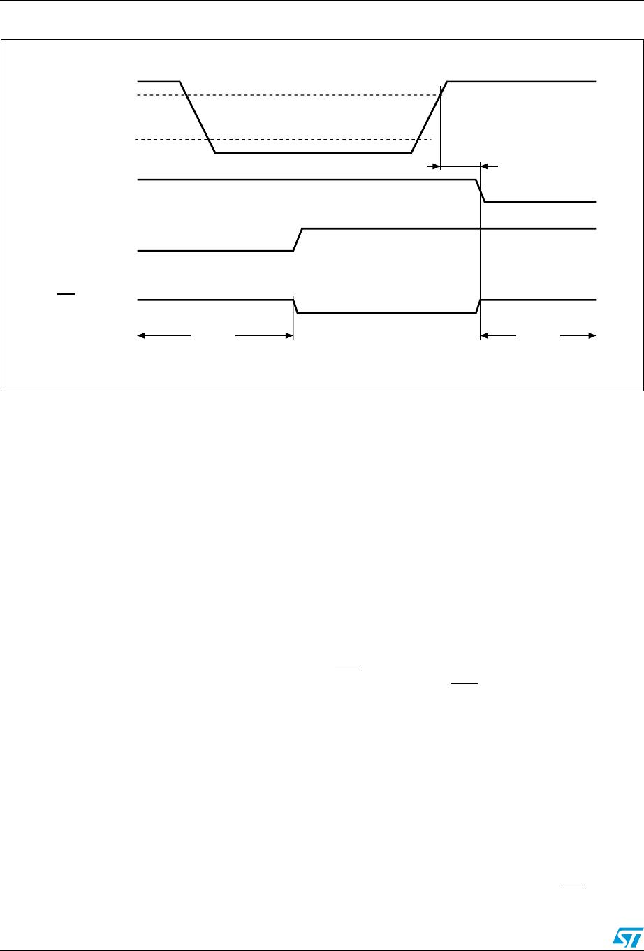
power-up. Figure 16 on page 24 illustrates the backup mode alarm timing.
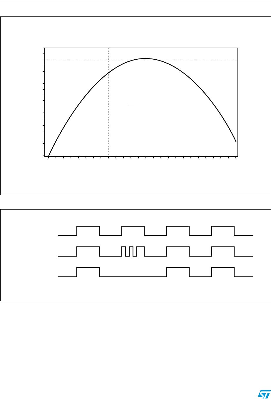
Figure 15. Alarm interrupt reset waveform
Table 3. Alarm repeat modes
RPT5 RPT4 RPT3 RPT2 RPT1 Alarm setting
11111Once per second
11110Once per minute
11100Once per hour
11000Once per day
10000Once per month
00000Once per year
AI03664
IRQ/FT/OUT
ACTIVE FLAG
0Fh0Eh 10h
HIGH-Z
Clock operation M41ST85W
24/43 Doc ID 7531 Rev 11
Figure 16. Backup mode alarm waveform
3.5 Watchdog timer
The watchdog timer can be used to detect an out-of-control microprocessor. The user
programs the watchdog timer by setting the desired amount of time-out into the watchdog
register, address 09h. Bits BMB4-BMB0 store a binary multiplier and the two lower order bits
RB1-RB0 select the resolution, where 00 = 1/16 second, 01 = 1/4 second, 10 = 1 second,
and 11 = 4 seconds. The amount of time-out is then determined to be the multiplication of
the five-bit multiplier value with the resolution. (For example: writing 00001110 in the
watchdog register = 3*1 or 3 seconds).
Note: The accuracy of the timer is within ± the selected resolution.
If the processor does not reset the timer within the specified period, the M41ST85W sets the
WDF (watchdog flag) and generates a watchdog interrupt or a microprocessor reset.
The most significant bit of the watchdog register is the watchdog steering bit (WDS). When
set to a '0,' the watchdog will activate the IRQ
/FT/OUT pin when timed-out. When WDS is
set to a '1,' the watchdog will output a negative pulse on the RST
pin for t
rec
. The watchdog
register, FT, AFE, ABE and SQWE bits will reset to a '0' at the end of a watchdog time-out
when the WDS bit is set to a '1.'
The watchdog timer can be reset by two methods: 1) a transition (high-to-low or low-to-high)
can be applied to the watchdog input pin (WDI) or 2) the microprocessor can perform a
WRITE of the watchdog register. The time-out period then starts over.
Note: The WDI pin should be tied to V
SS
if not used.
In order to perform a software reset of the watchdog timer, the original time-out period can
be written into the watchdog register, effectively restarting the count-down cycle.
Should the watchdog timer time-out, and the WDS bit is programmed to output an interrupt,
a value of 00h needs to be written to the watchdog register in order to clear the IRQ
/FT/OUT
AI03920
V
CC
IRQ/FT/OUT
V
PFD
ABE, AFE Bits in Interrupt Register
AF bit in Flags Register
HIGH-Z
V
SO
HIGH-Z
trec

M41ST85WMH6F

Mfr. #:
Manufacturer:
STMicroelectronics
Description:
Real Time Clock Serial 512 (64x8)
Lifecycle:
New from this manufacturer.
Delivery:
DHL FedEx Ups TNT EMS
Payment:
T/T Paypal Visa MoneyGram Western Union

Products related to this Datasheet