10
FN8177.7
October 7, 2015
Submit Document Feedback
X9313
Package Outline Drawing
M8.118
8 LEAD MINI SMALL OUTLINE PLASTIC PACKAGE
Rev 4, 7/11
DETAIL "X"
SIDE VIEW 2
TYPICAL RECOMMENDED LAND PATTERN
TOP VIEW
PIN# 1 ID
0.25 - 0.36
DETAIL "X"
0.10 ± 0.05
(4.40)
(3.00)
(5.80)
H
C
1.10 MAX
0.09 - 0.20
3°±3°
GAUGE
PLANE
0.25
0.95 REF
0.55 ± 0.15
B
0.08 C A-B
D
3.0±0.05
12
8
0.85±010
SEATING PLANE
A
0.65 BSC
3.0±0.05
4.9±0.15
(0.40)
(1.40)
(0.65)
D
5
5
SIDE VIEW 1
Dimensioning and tolerancing conform to JEDEC MO-187-AA
Plastic interlead protrusions of 0.15mm max per side are not
Dimensions in ( ) are for reference only.
Dimensions are measured at Datum Plane "H".
Plastic or metal protrusions of 0.15mm max per side are not
Dimensions are in millimeters.
3.
4.
5.
6.
NOTES:
1.
2.
and AMSEY14.5m-1994.
included.
included.
0.10 C
M
11
FN8177.7
October 7, 2015
Submit Document Feedback
X9313
Package Outline Drawing
M8.15
8 LEAD NARROW BODY SMALL OUTLINE PLASTIC PACKAGE
Rev 4, 1/12
DETAIL "A"
TOP VIEW
INDEX
AREA
123
-C-
SEATING PLANE
x 45°
NOTES:
1. Dimensioning and tolerancing per ANSI Y14.5M-1994.
2. Package length does not include mold flash, protrusions or gate burrs.
Mold flash, protrusion and gate burrs shall not exceed 0.15mm (0.006
inch) per side.
3. Package width does not include interlead flash or protrusions. Interlead
flash and protrusions shall not exceed 0.25mm (0.010 inch) per side.
4. The chamfer on the body is optional. If it is not present, a visual index
feature must be located within the crosshatched area.
5. Terminal numbers are shown for reference only.
6. The lead width as measured 0.36mm (0.014 inch) or greater above the
seating plane, shall not exceed a maximum value of 0.61mm (0.024 inch).
7. Controlling dimension: MILLIMETER. Converted inch dimensions are not
necessarily exact.
8. This outline conforms to JEDEC publication MS-012-AA ISSUE C.
SIDE VIEW “A
SIDE VIEW “B”
1.27 (0.050)
6.20 (0.244)
5.80 (0.228)
4.00 (0.157)
3.80 (0.150)
0.50 (0.20)
0.25 (0.01)
5.00 (0.197)
4.80 (0.189)
1.75 (0.069)
1.35 (0.053)
0.25(0.010)
0.10(0.004)
0.51(0.020)
0.33(0.013)
0.25 (0.010)
0.19 (0.008)
1.27 (0.050)
0.40 (0.016)
1.27 (0.050)
5.20(0.205)
1
2
3
4
5
6
7
8
TYPICAL RECOMMENDED LAND PATTERN
2.20 (0.087)
0.60 (0.023)
12
All Intersil U.S. products are manufactured, assembled and tested utilizing ISO9001 quality systems.
Intersil Corporation’s quality certifications can be viewed at www.intersil.com/design/quality
Intersil products are sold by description only. Intersil Corporation reserves the right to make changes in circuit design, software and/or specifications at any time without
notice. Accordingly, the reader is cautioned to verify that data sheets are current before placing orders. Information furnished by Intersil is believed to be accurate and
reliable. However, no responsibility is assumed by Intersil or its subsidiaries for its use; nor for any infringements of patents or other rights of third parties which may result
from its use. No license is granted by implication or otherwise under any patent or patent rights of Intersil or its subsidiaries.
For information regarding Intersil Corporation and its products, see www.intersil.com
FN8177.7
October 7, 2015
Submit Document Feedback
X9313
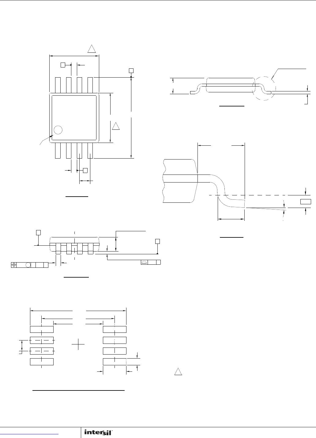
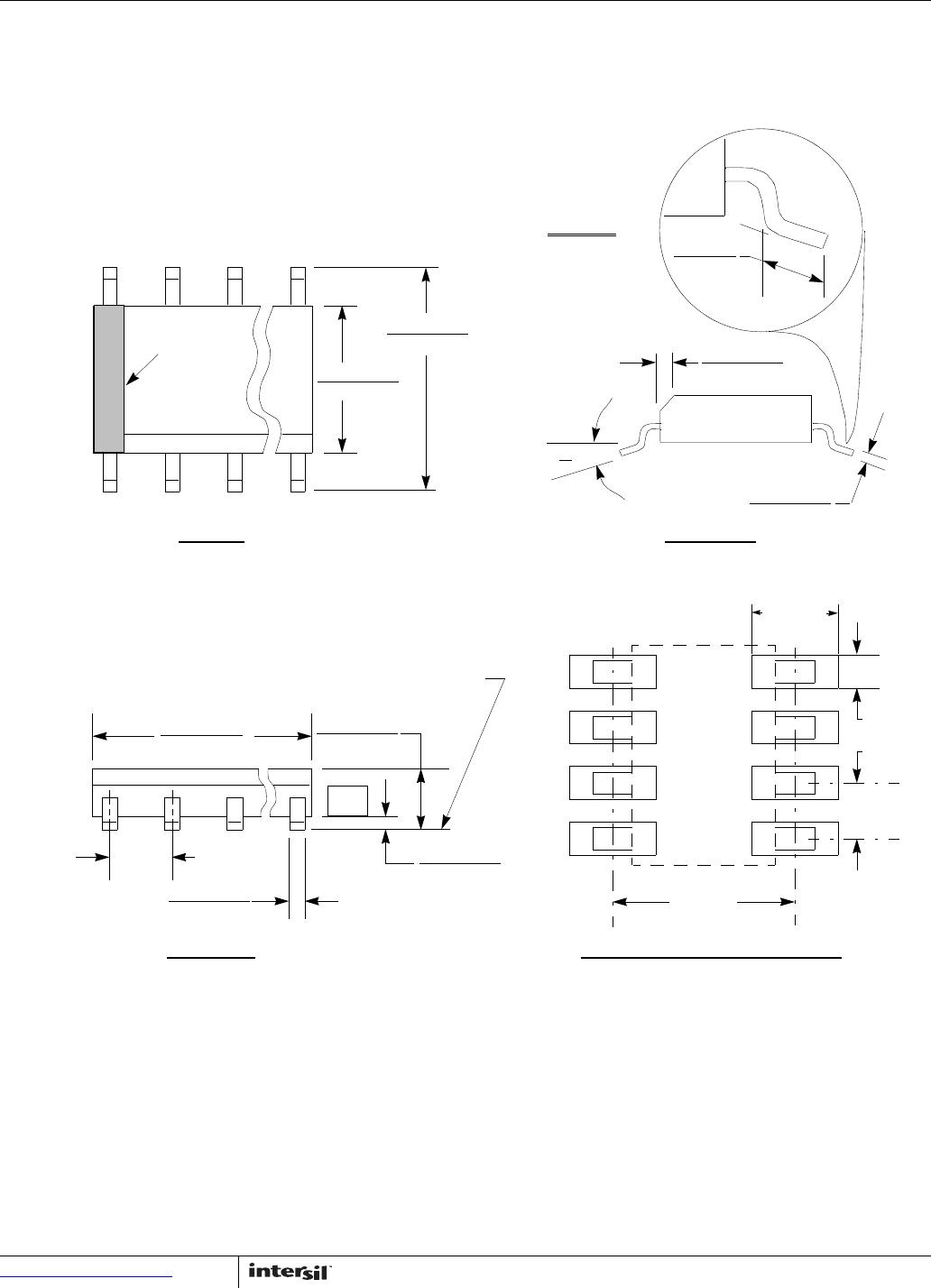
Plastic Dual-In-Line Packages (PDIP)
MDP0031
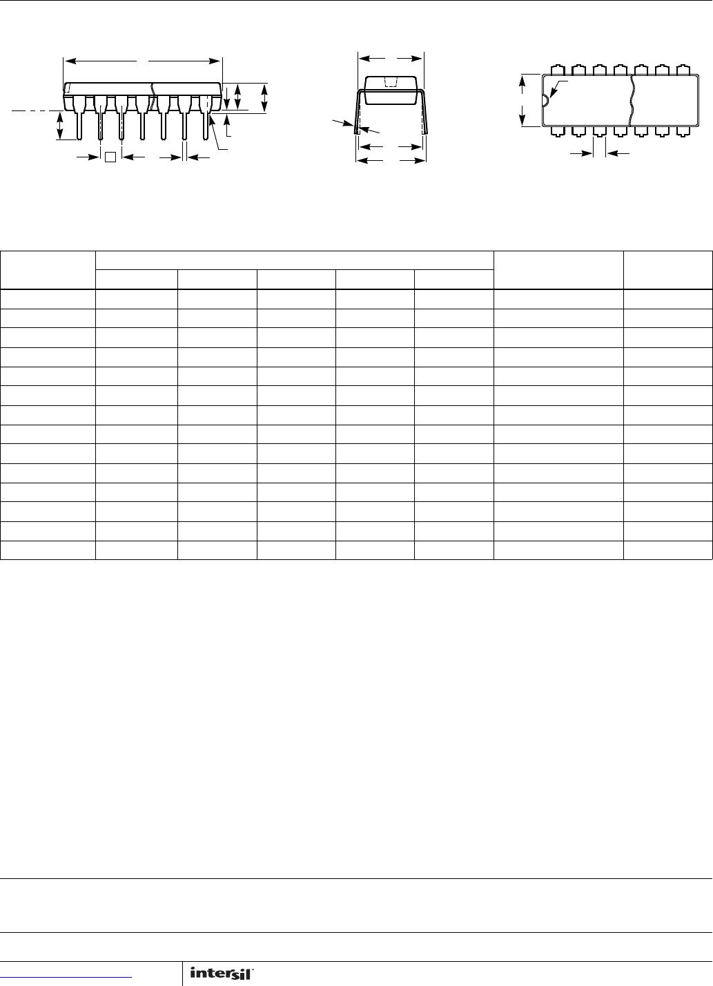
PLASTIC DUAL-IN-LINE PACKAGE
SYMBOL
INCHES
TOLERANCE NOTESPDIP8 PDIP14 PDIP16 PDIP18 PDIP20
A 0.210 0.210 0.210 0.210 0.210 MAX
A1 0.015 0.015 0.015 0.015 0.015 MIN
A2 0.130 0.130 0.130 0.130 0.130 ±0.005
b 0.018 0.018 0.018 0.018 0.018 ±0.002
b2 0.060 0.060 0.060 0.060 0.060 +0.010/-0.015
c 0.010 0.010 0.010 0.010 0.010 +0.004/-0.002
D 0.375 0.750 0.750 0.890 1.020 ±0.010 1
E 0.310 0.310 0.310 0.310 0.310 +0.015/-0.010
E1 0.250 0.250 0.250 0.250 0.250 ±0.005 2
e 0.100 0.100 0.100 0.100 0.100 Basic
eA 0.300 0.300 0.300 0.300 0.300 Basic
eB 0.345 0.345 0.345 0.345 0.345 ±0.025
L 0.125 0.125 0.125 0.125 0.125 ±0.010
N 8 14 16 18 20 Reference
Rev. C 2/07
NOTES:
1. Plastic or metal protrusions of 0.010” maximum per side are not included.
2. Plastic interlead protrusions of 0.010” maximum per side are not included.
3. Dimensions E and eA are measured with the leads constrained perpendicular to the seating plane.
4. Dimension eB is measured with the lead tips unconstrained.
5. 8 and 16 lead packages have half end-leads as shown.
D
L
A
e
b
A1
NOTE 5
A2
SEATING
PLANE
L
N
PIN #1
INDEX
E1
12 N/2
b2
E
eB
eA
c

X9313ZMZT1

Mfr. #:
Manufacturer:
Renesas / Intersil
Description:
Digital Potentiometer ICs CMOS EEPOT 1KOHM 32 TAPS
Lifecycle:
New from this manufacturer.
Delivery:
DHL FedEx Ups TNT EMS
Payment:
T/T Paypal Visa MoneyGram Western Union