Exar
Corporation 48720 Kato Road, Fremont CA, 94538
•
(510) 668-7000
•
FAX (510) 668-7017
•
www.exar.com
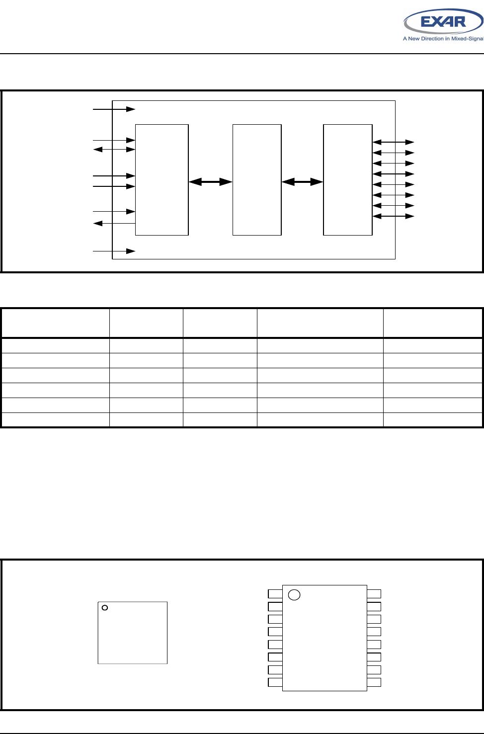
XRA1202/1202P
8-BIT I2C/SMBUS GPIO EXPANDER WITH RESET
APRIL 2013 REV. 1.0.1
GENERAL DESCRIPTION
The XRA1202/1202P is an 8-bit GPIO expander with
an I
2
C/SMBus interface. After power-up, the
XRA1202 has internal 100K ohm pull-up resistors on
each I/O pin that can be individually enabled. The
XRA1202P has the internal pull-up resistors enabled
upon power-up in case it is necessary for the inputs
to be in a known state.
In addition, the GPIOs on the XRA1202/1202P can
individually be controlled and configured. As outputs,
the GPIOs can be outputs that are high, low or in
three-state mode. The three-state mode feature is
useful for applications where the power is removed
from the remote devices, but they may still be
connected to the GPIO expander.
As inputs, the internal pull-up resistors can be
enabled or disabled and the input polarity can be
inverted. The interrupt can be programmed for
different behaviors. The interrupts can be
programmed to generate an interrupt on the rising
edge, falling edge or on both edges. The interrupt
can be cleared if the input changes back to its original
state or by reading the current state of the inputs.
The XRA1202/1202P are enhanced versions of the
PCA9538. The XRA1202 is pin and software
compatible with the PCA9538 (note: software
registers are compatible to the PCA9538, but the I
2
C
slave address is different).
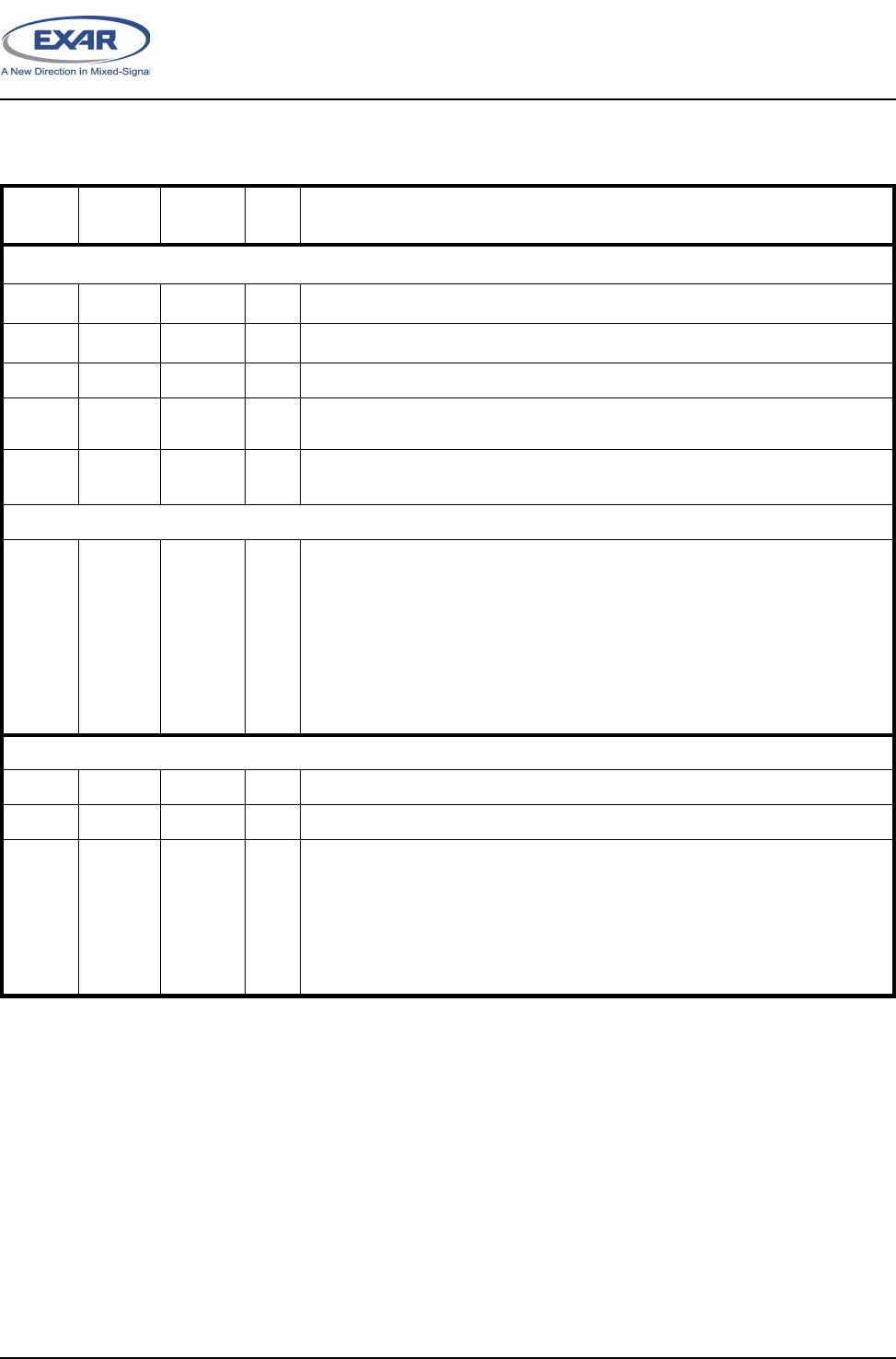
The XRA1202 is available in 16-pin QFN and 16-pin
TSSOP packages. The XRA1202P is available in the
16-pin QFN package.
FEATURES
•
1.65V to 3.6V operating voltage
•
8 General Purpose I/Os (GPIOs)
•
5V tolerant inputs
•
Maximum stand-by current of 1uA at +1.8V
•
I
2
C/SMBus bus interface
■
I
2
C clock frequency up to 400kHz
■
Noise filter on SDA and SCL inputs
■
Up to 16 I
2
C Slave Addresses
•
Individually programmable inputs
■
Internal pull-up resistors
■
Polarity inversion
■
Individual interrupt enable
■
Rising edge and/or Falling edge interrupt
■
Input filter
•
Individually programmable outputs
■
Output Level Control
■
Output Three-State Control
•
Open-drain active low interrupt output
•
Active-low reset input
•
Pin and software compatible with PCA9538
•
3kV HBM ESD protection per JESD22-A114F
•
200mA latch-up performance per JESD78B
APPLICATIONS
•
Personal Digital Assistants (PDA)
•
Cellular Phones/Data Devices
•
Battery-Operated Devices
•
Global Positioning System (GPS)
•
Bluetooth