LTC6993-1/LTC6993-2
LTC6993-3/LTC6993-4
5
69931234fc
For more information www.linear.com/LTC6993-1
elecTrical characTerisTics
Note 1: Stresses beyond those listed under Absolute Maximum Ratings
may cause permanent damage to the device. Exposure to any Absolute
Maximum Rating condition for extended periods may affect device
reliability and lifetime.
Note 2: The LTC6993C is guaranteed functional over the operating
temperature range of –40°C to 85°C.
Note 3: The LTC6993C is guaranteed to meet specified performance from
0°C to 70°C. The LTC6993C is designed, characterized and expected to
meet specified performance from –40°C to 85°C but it is not tested or
QA sampled at these temperatures. The LTC6993I is guaranteed to meet
specified performance from –40°C to 85°C. The LTC6993H is guaranteed
to meet specified performance from –40°C to 125°C. The LTC6993MP is
guaranteed to meet specified performance from –55°C to 125°C.
Note 4: Pulse width accuracy is defined as the deviation from the t
OUT
equation, assuming R
SET
is used to program the pulse width.
Note 5: See Operation section, Table 1 and Figure 2 for a full explanation
of how the DIV pin voltage selects the value of DIVCODE.
The l denotes the specifications which apply over the full operating
temperature range, otherwise specifications are at T
A
= 25°C. Test conditions are V
+
= 2.25V to 5.5V, TRIG = 0V, DIVCODE = 0 to 15
(N
DIV
= 1 to 2
21
), R
SET
= 50k to 800k, R
LOAD
= ∞, C
LOAD
= 5pF unless otherwise noted.
Note 6: The TRIG pin has hysteresis to accommodate slow rising or falling
signals. The threshold voltages are proportional to V
+
. Typical values can
be estimated at any supply voltage using:
V
TRIG(RISING)
≈ 0.55 • V
+
+ 185mV and
V
TRIG(FALLING)
≈ 0.48 • V
+
– 155mV
Note 7: To conform to the Logic IC Standard, current out of a pin is
arbitrarily given a negative value.
Note 8: Output rise and fall times are measured between the 10% and the
90% power supply levels with 5pF output load. These specifications are
based on characterization.
Note 9: Settling time is the amount of time required for the output to settle
within ±1% of the final pulse width after a 0.5× or 2× change in I
SET
.
Note 10: Jitter is the ratio of the deviation of the output pulse width to the
mean of the pulse width. This specification is based on characterization
and is not 100% tested.
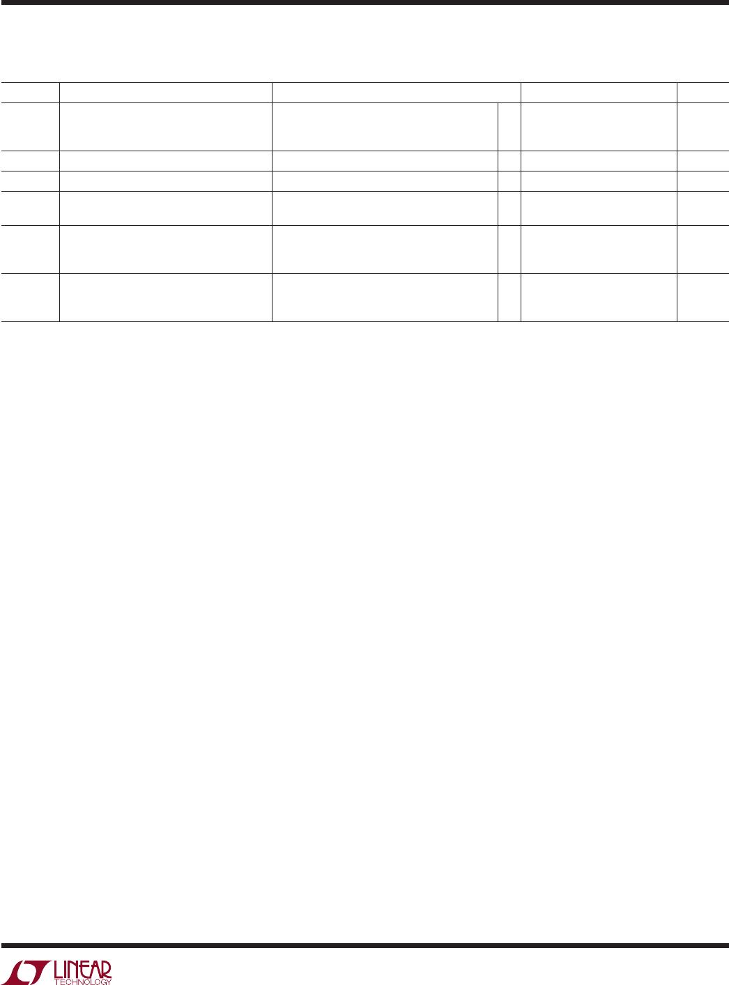
SYMBOL PARAMETER CONDITIONS MIN TYP MAX UNITS
t
PD
Trigger Propagation Delay V
+
= 5.5V
V
+
= 3.3V
V
+
= 2.25V
11
17
28
ns
ns
ns
t
WIDTH
Minimum Recognized TRIG Pulse Width V
+
= 3.3V 5 ns
t
ARM
Recovery Time (LTC6993-1/LTC6993-3) –4 ns
t
RETRIG
Time Between Trigger Signals
(LTC6993-2/LTC6993-4)
N
DIV
= 1 V
+
= 3.3V
N
DIV
> 1 V
+
= 3.3V
10
50
ns
ns
t
r
Output Rise Time (Note 8) V
+
= 5.5V
V
+
= 3.3V
V
+
= 2.25V
1.1
1.7
2.7
ns
ns
ns
t
f
Output Fall Time (Note 8) V
+
= 5.5V
V
+
= 3.3V
V
+
= 2.25V
1.0
1.6
2.4
ns
ns
ns