LTC2950-1/LTC2950-2
10
295012fd
Figure 1. Simplified Power On/Off Sequence for LTC2950-1
Figure 2. Aborted Power On Sequence for LTC2950-1
t
ABORT
PB
KILL
POWER ON
TIMING
EN
512ms
INTERNAL
TIMER
t
DB, ON
+ t
ONT
POWER
TURNED OFF
2950 F02
µP FAILED TO SET
KILL HIGH
t
1
t
2
t
DB, ON
t
ONT
t
3
t
4
t
5
t
6
t
7
PB
ONT
OFFT
EN
KILL
INT
PB & KILL IGNORED PB IGNORED
2950 F01
t
KILL, ON BLANK
t
DB, OFF
t
OFFT
<t
KILL, OFF DELAY
< t
KILL
,
OFF DELAY
applicaTions inForMaTion
LTC2950-1/LTC2950-2
11
295012fd
Figure 4 shows the µP turning power off. After a low on
KILL releases enable, the internal 256ms timer ignores
the PB pin. This is shown as t
EN/EN
, LOCKOUT in Figure 4.
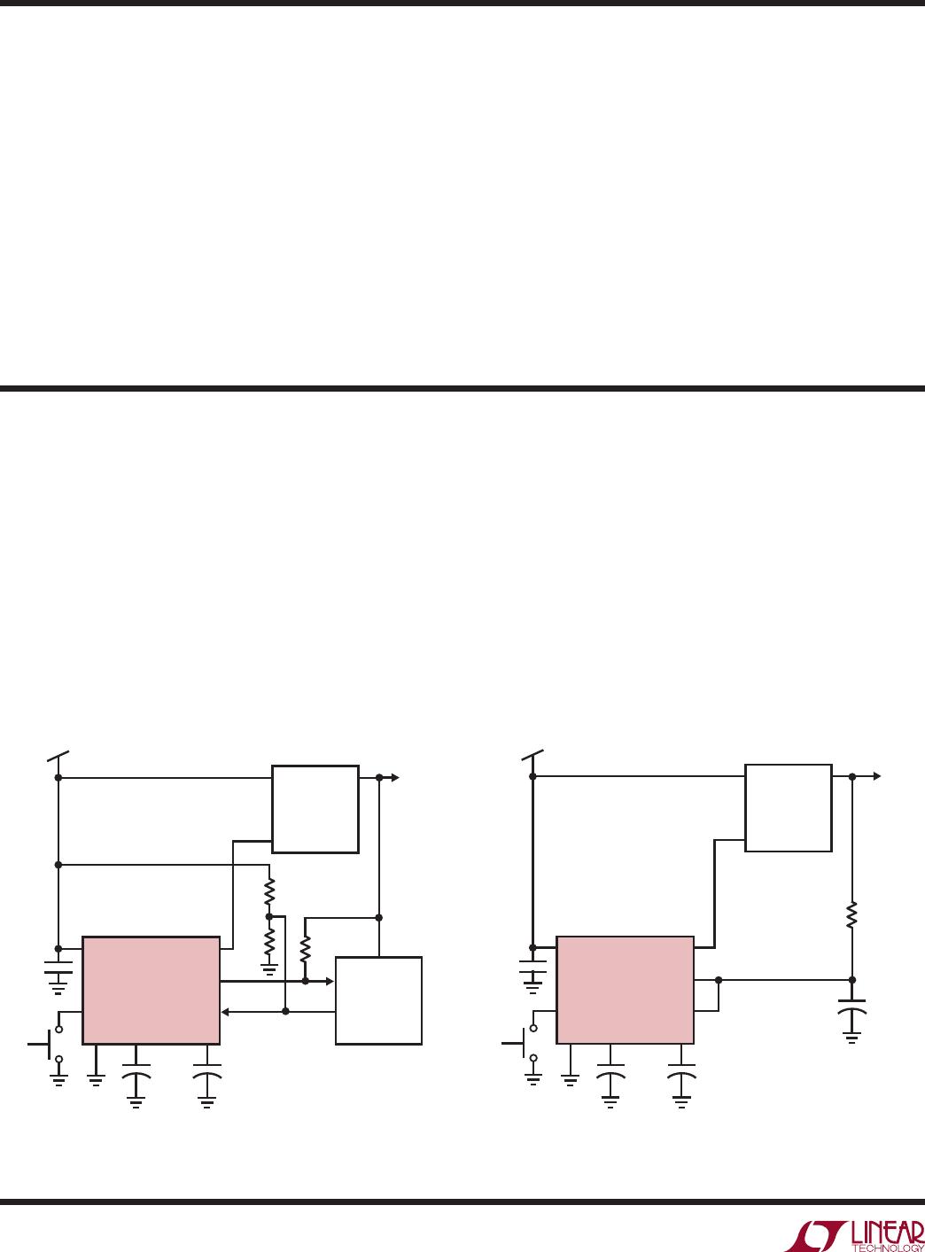
LTC2950-1, LTC2950-2 VERSIONS
The LTC2950-1 (high true EN) and LTC2950-2 (low true
EN) differ only by the polarity of the EN/EN pin. Both ver-
sions allow the user to extend the amount of time that the
PB must be held low in order to begin a valid power on/
off sequence. An external capacitor placed on the ONT
pin adds additional time to the turn on time. An external
capacitor placed on the OFFT pin adds additional time to
the turn off time. If no capacitor is placed on the ONT
(OFFT) pin, then the turn on (off) duration is given by an
internally fixed 32ms timer.
The LTC2950 fixes the KILL turn off delay time (t
KILL, OFF
DELAY
) at 1024ms. This means that the EN/EN pin will be
switched low/high a maximum of 1024ms after initiating
a valid turn off sequence. Note that in a typical application,
a µP or µC would set KILL low prior to the 1024ms timer
period (t
7
in Figure 1).
Figure 3. µP Turns Off Power (LTC2950-1)
t
KILL
PB
EN
DC/DC
TURNS OFF
2950 F03
KILL
XXX DON’T CARE
µP SETS
KILL LOW
PB
PB IGNORED
EN
KILL
PB BLANKING
XXX DON’T CARE
256ms
POWER ON
2950 F04
DC/DC
TURNS OFF
µP SETS
KILL LOW
t
EN/EN, LOCKOUT
Figure 4. DC/DC Turn Off Blanking (LTC2950-1)
Aborted Power On Sequence
The power on sequence is aborted when the KILL remains
low after the end of the 512ms blanking time. Figure 2 is
a simplified version of an aborted power on sequence.
At time t
ABORT,
since KILL is still low, EN pulls low (thus
turning off the DC/DC converter).
µP Turns Off Power During Normal Operation
Once the system has powered on and is operating nor-
mally, the µP can turn off power by setting KILL low, as
shown in Figure 3. At time t
KILL
, KILL is set low by the µP.
This immediately pulls EN low, thus turning off the DC/
DC converter.
DC/DC Turn Off Blanking
When the DC/DC converter is turned off, it can take a sig-
nificant amount of time for its output to decay to ground. It
is desirable to wait until the output of the DC/DC converter
is near ground before allowing the user (via PB) to restart
the converter. This condition guarantees that the µP has
always powered down completely before it is restarted.
applicaTions inForMaTion
LTC2950-1/LTC2950-2
12
295012fd
The following equations describe the turn on and turn
off times. C
ONT
and C
OFFT
are the external programming
capacitors:
t
BD,ON
+ t
ONT
= 32ms + 1ms + (6.7x10
6
) • C
ONT
t
BD,OFF
+ t
OFFT
= 32ms + 1ms + (6.7x10
6
) • C
OFFT
High Voltage Pins
The V
IN
and PB pins can operate at voltages up to 26.4V.
PB can, additionally, operate below ground (–6V) without
latching up the device. PB has an ESD HBM rating of ±10kV.
If the pushbutton switch connected to PB exhibits high
leakage current, then an external pull-up resistor to V
IN
is
recommended. Furthermore, if the pushbutton switch is
physically located far from the LTC2950 PB pin, parasitic
capacitances may couple onto the high impedance PB
input. Additionally, parasitic series inductance may cause
unpredictable ringing at the PB pin. Placing a 5k resistor
from the PB pin to the pushbutton switch would mitigate
parasitic inductance problems. Placing a 0.1µF capacitor
on the PB pin would lessen the impact of parasitic capaci-
tive coupling.
Voltage Monitoring with KILL Input
The KILL pin can be used as a voltage monitor. Figure 5
shows an application where the KILL pin has a dual function.
It is driven by a low leakage open drain output of the µP. It
is also connected to a resistor divider that monitors battery
voltage (V
IN
). When the battery voltage falls below the set
value, the voltage at the KILL pin falls below 0.6V and the
EN pin is quickly pulled low. Note that the resistor values
should be as large as possible, but small enough to keep
leakage currents from tripping the 0.6V KILL comparator.
The DC/DC converter shown has an internal pull-up current
on its SHDN pin. A pull-up resistor on EN is thus not needed.
Operation Without µP
Figure 6 shows how to connect the KILL pin when there
is no circuitry available to drive it. The minimum pulse
width detected is 30µs. If there are glitches on the resistor
pull-up voltage that are wider than 30µs and transition
Figure 5. Input Voltage Monitoring with KILL Input Figure 6. No µP Application
PB
V
IN
SHDN**
V
IN
V
OUT
EN
INT
KILL
INT
KILL
(OPEN DRAIN)
LTC2950-1
GND ONT OFFT
LT1767-3.3
µP
9V
R1
10k
3.3V
2950 F05
C4
0.1µF
R3
806k
1%
R2
100k
1%
5.4V THRESHOLD
V
IN
C
ONT
*
0.033µF
C
OFFT
*
0.033µF
*OPTIONAL
**SHDN INTERNALLY PULLED UP BY THE LT1767-3.3
V
IN
SHDN**
V
IN
V
OUT
LT1767-3.3
9V
3.3V
R1
100k
C3*
0.01µF
2950 F06
+
C4
0.1µF
PB
EN
INT
KILL
LTC2950-1
GND ONT OFFT
V
IN
C
ONT
*
0.033µF
C
OFFT
*
0.033µF
*OPTIONAL
**SHDN INTERNALLY PULLED UP BY THE LT1767-3.3
applicaTions inForMaTion
Typical applicaTions

LTC2950CDDB-2#TRMPBF

Mfr. #:
Manufacturer:
Analog Devices Inc.
Description:
Supervisory Circuits Basic Push Button On/Off Controller (Adjustbale On and Off Timers)
Lifecycle:
New from this manufacturer.
Delivery:
DHL FedEx Ups TNT EMS
Payment:
T/T Paypal Visa MoneyGram Western Union