Automotive High Current LED Controller
A6265
10
Allegro MicroSystems, LLC
115 Northeast Cutoff
Worcester, Massachusetts 01615-0036 U.S.A.
1.508.853.5000; www.allegromicro.com
Diagnostics
The circuit includes several diagnostic and safety functions to
assist in ensuring safe operation of the LEDs, the A6265, and the
external components. When any fault is detected, one or both of
the fault flag outputs, FF1 and FF2, will be inactive (high imped-
ance, open drain) until the fault is removed. The action taken by
the A6265 when a fault occurs is defined in table 1. To be able to
monitor the state of FF1 and FF2, add a suitable external pull-up
resistor.
The A6265 will continue to drive the LEDs under most fault con-
ditions and will only disable the drive to the LEDs when a high
voltage hazard is present or the external components are likely to
be over-stressed. For output short circuits or open LED condi-
tions, the fault status is latched until EN is taken low or a power
cycle occurs. For output short circuits or a shorted LED string,
the fault status is latched until either EN is taken low for a period
greater than the disable time, or a power cycle occurs.
At start-up, a Fault Blank period, t
FB ,
occurs before the fault
detection circuitry becomes active. This period allows steady
state conditions to be established before fault monitoring takes
place.
Note that no fault blanking is applied to open LED faults. This
is generally not an issue because the charging of the output filter
capacitor provides a degree of filtering. In addition, extremely
high voltages are prevented from causing potential device break-
down, for example in the external switching MOSFET.
VREG Undervoltage If the voltage at VREG, V
REG
, drops
below the specified turnoff voltage, V
REGUV
, the gate drive
output, SG, will be driven low and both fault flags, FF1 and
FF2, will be high impedance. V
REG
must rise above the turn-on
threshold, V
REGUV
+ V
REGUV
, before the output circuits are
activated. This ensures that the external FET is operating in its
fully enhanced state and avoids permanent damage to the FET,
caused by overheating.
LED Undercurrent Under some circuit conditions, particularly
during a low input voltage condition, it is possible that there
could be insufficient drive to maintain the current to the LEDs
at the required level. If the voltage across the LED current sense
resistor, R
SS
, falls below the target sense voltage, V
IDL
, by an
amount that is more than the LED undercurrent voltage differ-
ence, V
UCL
, the A6265 will indicate an LED undercurrent condi-
tion by setting FF2 to high impedance. However, the A6265 will
continue to drive the output. When the output again reaches the
required current level, FF2 will go low.
Overtemperature Warning If the chip temperature exceeds
the overtemperature threshold, T
JF
, fault flag FF2 will be high
impedance. No action will be taken by the A6265 to limit the
chip temperature. An external control circuit must take action
to avoid permanent damage to the A6265 and/or the LEDs. The
temperature will continue to be monitored and the fault flags will
be deactivated when the temperature drops below the recovery
threshold provided by the hysteresis, T
Jhys
.
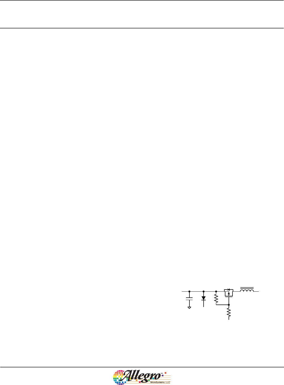
LED Diagnostics The status of the LEDs in the load can be
determined by monitoring the voltage with respect to ground at
the three pins LP, LF, and LA, namely V
LP
, V
LF
, and V
LA
. These
voltages provide two differential voltage measurements:
• the voltage across a single reference LED:
V
LED
= V
LF
V
LP
(5)
• the ratio of the voltage across all LEDs in a single string:
V
STR
= V
LA
V
LP
(6)
The voltage, V
STR
, is derived from the voltage across all LEDs in
the string, by an external resistor divider with a ratio equal to the
quantity of LEDs in the string. To minimize the effects of the bias
currents introducing an offset voltage, it is recommended that the
resistor between LP and LA should be approximately 560 .
So for example, if eight LEDs were used, the ratio required
would be an eighth, therefore the resistor connected between LA
and the anode end of the LED string would be 3.9 k;
560 / [560 + 3900] = 1/8 .
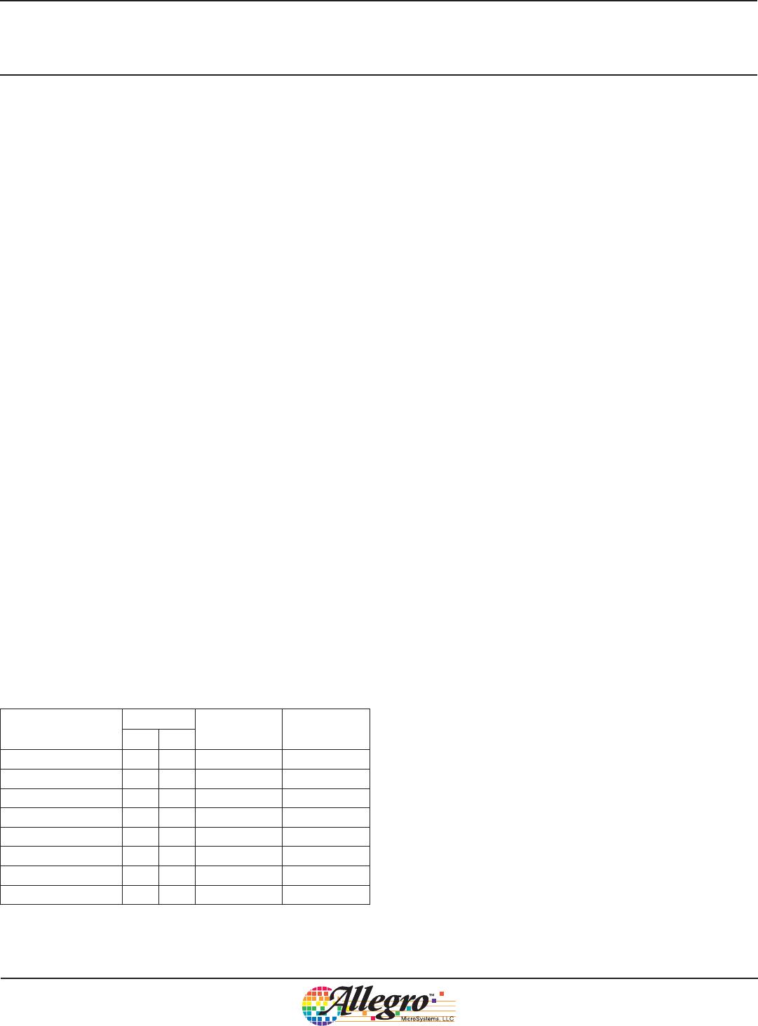
Table 1. Fault Table
Fault
Pin
Action Latched
FF1 FF2
No Fault L L No Action
VREG Undervoltage Z Z Disable* No
Output Short Z L Disable* Yes
LED Undercurrent L Z No Action No
Overtemperature L Z No Action No
Open LED L Z Disable* Yes
Shorted LED L Z No Action No
Shorted LED String Z L Disable* Yes
* SG low, MOSFET off
L = active pull-down, Z = inactive, open drain
Automotive High Current LED Controller
A6265
11
Allegro MicroSystems, LLC
115 Northeast Cutoff
Worcester, Massachusetts 01615-0036 U.S.A.
1.508.853.5000; www.allegromicro.com
These measurements are used to determine if there is an open
circuit, if one or more LEDs are shorted, if the output is shorted,
or if there is a short across the LED string. Each condition is
described in turn in the following sections.
Open LED–An open circuit is evaluated when:
V
STR
> V
OCL
(7)
where V
OCL
is the LED open circuit voltage defined in the Elec-
trical Characteristics table.
Because the output is current-controlled it is possible for an open
circuit on the output to cause extremely high voltages to be pres-
ent. Therefore, to prevent any hazardous voltages or damage to
the circuits, the gate drive output, SG, is immediately driven low
when an open circuit is detected. After an open circuit fault has
been detected, FF2 will become high impedance, and the open
circuit fault state will remain until the open fault time-out period
toto, expires. When the gate drive output is re-enabled at the end
of the open fault time-out period, the output is again monitored
for an open circuit. If the open circuit is still present, then the
fault will again be flagged and the switch drive disabled. This
cycle will continue, as long as the open circuit condition is pres-
ent.
Note that the Fault Blank timer is not used when an open LED
fault occurs. This is to avoid potentially damaging voltages
appearing in the power circuitry.
Shorted LEDA short circuit on one or more LEDs is detected
when:
• for the first (reference) LED:
V
STR
> V
LED
+ V
SCOR
(8)
• for other than the first (reference) LED:
V
LED
> V
STR
+ V
SCO
(9)
where V
STR
and V
LED
are as defined above, V
SCO
is the nonrefer-
ence LED short offset voltage, and V
SCOR
is the reference LED
short offset voltage. V
SCO
and V
SCOR
are defined in the Electrical
Characteristics table.
When a short is present, the fault flag FF2 is high impedance, but
the regulator continues to operate and drives the remaining LEDs
with the correct regulated current. FF2 will remain high imped-
ance while the short circuit condition is present.
A short circuit on one or more LEDs will not cause a hazard
because the output is current-controlled. If one LED fails and
becomes a short circuit, then the remaining LEDs will continue
to be lit with the same current through, and voltage across,
each LED.
Note—Accuracy: The output status monitor relies on all the
LEDs in the load having a similar forward voltage drop. Where
possible all the LEDs forming the load for a single controller
should be taken from the same voltage bin. With only two or
three LEDs a wider variation in forward voltage is acceptable,
but the selection of LEDs from the same bin is more critical when
higher numbers of LEDs are used in a single string.
Shorted LED String or Output ShortA short circuit across
the LED string, is detected when:
V
STR
< V
SCL
(10)
An output short can consist of the LP, LN, or LF terminals of
the LED string being shorted, either to the battery terminal or
to ground. Either a shorted LED string or output short will be
latched and will only be cleared by pulling EN low for a period
greater than the disable time, or by cycling the power.
If either a shorted LED string, or an output short is detected, the
A6265 will stop the switching action by pulling SG low. The
fault flag FF1 will go high impedance and should be pulled up to
the supply with suitable external pull-up resistors to indicate the
fault. Either a shorted LED string or output short will be latched
and will only be cleared by pulling EN low for a period greater
than the disable time, or by cycling the power.
The FF1 output can also be used with pull-up resistors and a
P-channel MOSFET in the supply, to isolate the switching ele-
ments and the load from the supply. This MOSFET should be
connected, as shown in figure 3, with the source connected to the
supply and the drain connected to the inductor of the converter.
To FF1
VBAT
To VIN
Figure 3. Example of a supply isolation MOSFET
Automotive High Current LED Controller
A6265
12
Allegro MicroSystems, LLC
115 Northeast Cutoff
Worcester, Massachusetts 01615-0036 U.S.A.
1.508.853.5000; www.allegromicro.com
Two pull-up resistors are used to limit the voltage across the gate-
source junction during high input voltages or load dump condi-
tions. If the battery voltage is restricted, one resistor across the
gate-source junction can be used. The FF1 provides a sink current
of up to 1.3 mA.
This circuit can be used to avoid most hazardous conditions and
protect the circuit components from over-stress. Note that under
extreme cases, the circuit cannot protect against certain fault con-
ditions. For example, when any of the following occurs:
• In boost mode:
If the cathode end of the LED string is shorted to VBAT, the
LED sense resistor effectively appears between VBAT and
ground. Depending on the current limit of the source supply or
the input fuse rating, the fault current may damage the resistor.
If the LF node is shorted to VBAT, the reference LED and
the LED sense resistor effectively appear between VBAT and
ground. Depending on the current limit of the source supply or
the input fuse rating, the fault current may damage the resistor
and /or the reference LED.
If the cathode end of the LED string is shorted to ground. A
fault current determined by the impedance of the shorting link
(now effectively the LED sense resistor) flows through the
power circuit. The fault current will either: be limited by the
maximum switch current sense, V
IDS
, or if the source supply
cannot maintain this current, be limited by the source supply.
(The source supply will either: fold back, or if the current
exceeds the input fuse rating, the fuse will blow, creating an
open circuit).
• In buck-boost mode:
If the cathode end of the LED string is shorted to ground, the
LED sense resistor effectively appears between VBAT and
ground. Depending on the current limit of the source supply or
the input fuse rating, the fault current may damage the resistor.
If the LF node is shorted to ground, the reference LED and
the LED sense resistor effectively appear between VBAT and
ground. The reference LED will be reversed biased and will
probably be damaged.
If the cathode end of the LED string (LP) is shorted to VBAT,
the impedance of the short appears in parallel with the series
combination of the series protection MOSFET and the LED
sense resistor. This will tend to reduce the effective impedance
of the LED sense resistor and correspondingly increase the
LED current.
To ensure the A6265 inputs (LP and LN) are not damaged dur-
ing any of the above faults, it is necessary to add a differential
resistor in series with the LN connection (between the sense
resistor and the LN pin). This resistor value should be approxi-
mately 150 .
If an output short is detected but it is necessary to keep the output
active, the FF1 output can be pulled low. This will override the
output disable but will not clear the fault.

A6265KLPTR-T

Mfr. #:
Manufacturer:
Description:
IC LED DRIVER CTRLR DIM 16TSSOP
Lifecycle:
New from this manufacturer.
Delivery:
DHL FedEx Ups TNT EMS
Payment:
T/T Paypal Visa MoneyGram Western Union

Products related to this Datasheet