9DB833
EIGHT OUTPUT DIFFERENTIAL BUFFER FOR PCIE GEN1,2,3
IDT®
EIGHT OUTPUT DIFFERENTIAL BUFFER FOR PCIE GEN1,2,3 10
9DB833 REV H 06/07/16
Vdiff Vp-p Vcm R1 R2 R3 R4 Note
0.45v 0.22v 1.08 33 150 100 100
0.58 0.28 0.6 33 78.7 137 100
0.80 0.40 0.6 33 78.7 none 100 ICS874003i-02 input compatible
0.60 0.3 1.2 33 174 140 100 Standard LVDS
R1a = R1b = R1
R2a = R2b = R2
Termination for LVDS and other Common Differential Signals (figure 3)
HCSL Output Buffer
L1
L1'
R1b
L2
L2'
R1a
L4'
L4
L3
R2a R2b
Down Device
REF_CLK Input
Figure 3
L3'
R3 R4
Component Value Note
R5a, R5b 8.2K 5%
R6a, R6b 1K 5%
Cc 0.1 µF
Vcm 0.350 volts
Termination for Cable AC Coupled Application (figure 4)
PCIe Device
REF_CLK Input
Figure 4
R5a
L4'
L4
3.3 Volts
R5b
R6a R6b
Cc
Cc
9DB833
EIGHT OUTPUT DIFFERENTIAL BUFFER FOR PCIE GEN1,2,3
IDT®
EIGHT OUTPUT DIFFERENTIAL BUFFER FOR PCIE GEN1,2,3 11
9DB833 REV H 06/07/16
General SMBus Serial Interface Information
How to Write
Controller (host) sends a start bit
Controller (host) sends the write address*
IDT clock will acknowledge
Controller (host) sends the beginning byte location = N
IDT clock will acknowledge
Controller (host) sends the byte count = X
IDT clock will acknowledge
Controller (host) starts sending Byte N through Byte
N+X-1
IDT clock will acknowledge each byte one at a time
Controller (host) sends a Stop bit
* Assuming SMB_ADR_tri is at mid-level
How to Read
Controller (host) will send a start bit
Controller (host) sends the write address*
IDT clock will acknowledge
Controller (host) sends the beginning byte location = N
IDT clock will acknowledge
Controller (host) will send a separate start bit
Controller (host) sends the read address*
IDT clock will acknowledge
IDT clock will send the data byte count = X
IDT clock sends Byte N+X-1
IDT clock sends Byte 0 through Byte X (if X
(H)
was
written to Byte 8)
Controller (host) will need to acknowledge each byte
Controller (host) will send a not acknowledge bit
Controller (host) will send a stop bit
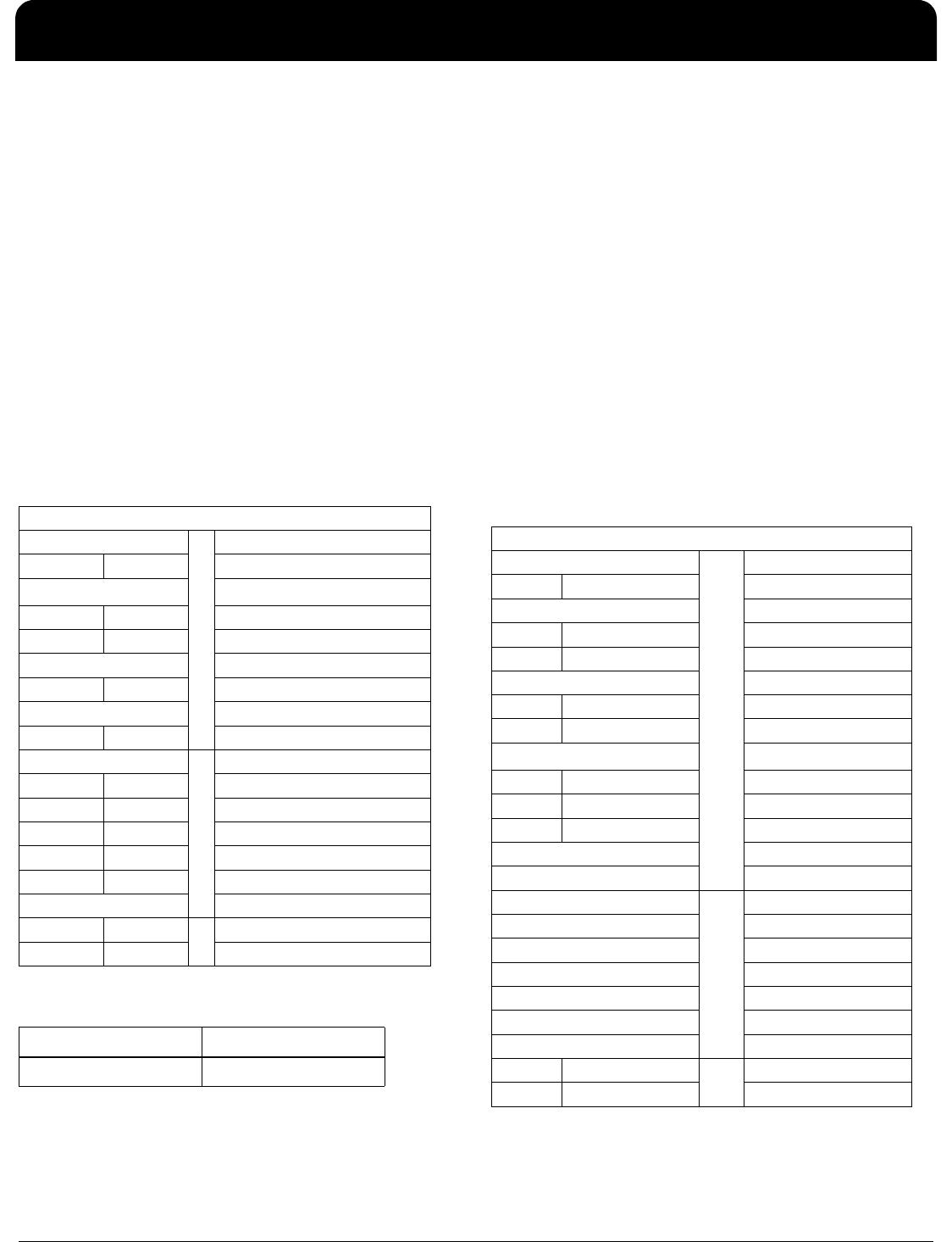
Index Block Write Operation
Controller (Host) IDT (Slave/Receiver)
TstarT bit
Slave Address
WR WRite
ACK
Beginning Byte = N
ACK
Data Byte Count = X
ACK
Beginning Byte N
X Byte
ACK
O
O O
O O
O
Byte N + X - 1
ACK
PstoP bit
Read Address Write Address
DD
(H)
DC
(H)
Index Block Read Operation
Controller (Host) IDT (Slave/Receiver)
TstarT bit
Slave Address
WR WRite
ACK
Beginning Byte = N
ACK
RT Repeat starT
Slave Address
RD ReaD
ACK
Data Byte Count=X
ACK
X Byte
Beginning Byte N
ACK
O
O O
O O
O
Byte N + X - 1
N Not acknowledge
PstoP bit
9DB833
EIGHT OUTPUT DIFFERENTIAL BUFFER FOR PCIE GEN1,2,3
IDT®
EIGHT OUTPUT DIFFERENTIAL BUFFER FOR PCIE GEN1,2,3 12
9DB833 REV H 06/07/16
SMBus Table: Frequency Select Register, READ/WRITE ADDRESS (Selectable)
Pin # Name Control Function T
yp
e 0 1 Defaul
t
Bit 7
PD_Mode PD# drive mode RW driven Hi-Z 1
Bit 6
OE_Mode OE#_Stop drive mode RW driven Hi-Z 0
Bit 5
0
Bit 4
X
Bit 3
MODE1 BYPASS#/PLL1 RW Latched
Bit 2
1
Bit 1
MODE0 BYPASS#/PLL0 RW Latched
Bit 0
SRC_DIV# SRC Divide by 2 Select RW x/2 x/1 1
SMBus Table: Output Control Register
Pin # Name Control Function T
yp
e 0 1 Defaul
t
Bit 7
DIF_7 Output Enable RW Disable Enable 1
Bit 6
DIF_6 Output Enable RW Disable Enable 1
Bit 5
DIF_5 Output Enable RW Disable Enable 1
Bit 4
DIF_4 Output Enable RW Disable Enable 1
Bit 3
DIF_3 Output Enable RW Disable Enable 1
Bit 2
DIF_2 Output Enable RW Disable Enable 1
Bit 1
DIF_1 Output Enable RW Disable Enable 1
Bit 0
DIF_0 Output Enable RW Disable Enable 1
NOTE:
The SMBus Output Enable Bit must be '1' AND the respective OE pin must be active for the output to run.
SMBus Table: OE Pin Control Register
Pin # Name Control Function T
yp
e 0 1 Defaul
t
Bit 7
DIF_7 DIF_7 Stoppable with OE7# RW Free-run Stoppable 0
Bit 6
DIF_6 DIF_6 Stoppable with OE6# RW Free-run Stoppable 0
Bit 5
DIF_5 DIF_5 Stoppable with OE5# RW Free-run Stoppable 0
Bit 4
DIF_4 DIF_4 Stoppable with OE4# RW Free-run Stoppable 0
Bit 3
DIF_3 DIF_3 Stoppable with OE3# RW Free-run Stoppable 0
Bit 2
DIF_2 DIF_2 Stoppable with OE2# RW Free-run Stoppable 0
Bit 1
DIF_1 DIF_1 Stoppable with OE1# RW Free-run Stoppable 0
Bit 0
DIF_0 DIF_0 Stoppable with OE0# RW Free-run Stoppable 0
NOTE:
If you wish the default to be "Stoppable" see the 9DB834.
SMBus Table: Reserved Register
Pin # Name Control Function T
yp
e 0 1 Defaul
t
Bit 7
X
Bit 6
X
Bit 5
X
Bit 4
X
Bit 3
X
Bit 2
X
Bit 1
X
Bit 0
X
Reserved
Reserved
Reserved
SeeOperating Mode
Readback Table
SeeOperating Mode
Readback Table
B
y
te 0
-
-
-
-
-
-
-
-
16,17
30,29
20,21
34,33
30,29
20,21
16,17
12,13
8,9
B
y
te 2
42,41
38,37
34,33
12,13
8,9
B
y
te 3
B
y
te 1
42,41
38,37
Reserved
Reserved
Reserved
Reserved
Reserved
Reserved
Reserved
Reserved

9DB833AGILF

Mfr. #:
Manufacturer:
IDT
Description:
Clock Buffer 8 OUTPUT PCIE GEN3 BUFFER
Lifecycle:
New from this manufacturer.
Delivery:
DHL FedEx Ups TNT EMS
Payment:
T/T Paypal Visa MoneyGram Western Union