Example Programs
1-6 Bluetooth EZ-Extender Manual
Bluetooth EZ-Extender Manual 2-1
2 BLUETOOTH EZ-EXTENDER
HARDWARE REFERENCE
This chapter describes the hardware design of the Bluetooth EZ-Extender.
The following topics are covered.
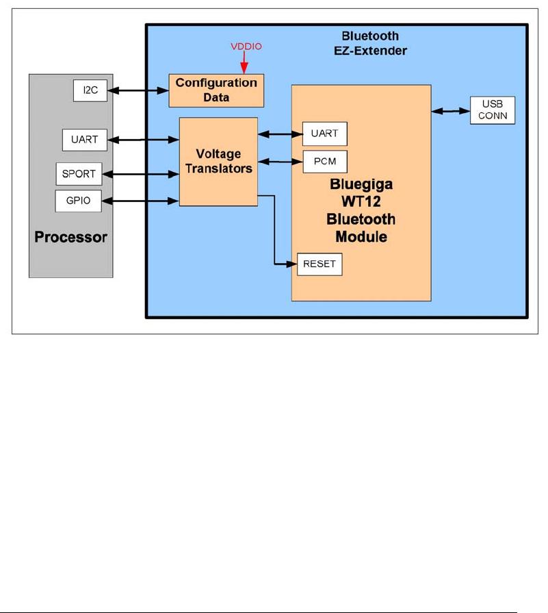
“System Architecture” on page 2-2
Describes the daughter board’s configuration and explains how the
board components interface with the processor and EZ-Board.
“Configuration Switch” on page 2-3
Shows the location and describes the board’s configuration switch.
“Jumpers” on page 2-5
Shows the location and describes the board’s jumpers.
“Power LED” on page 2-7
Shows the location and describes the board’s power LED.
“Connectors” on page 2-8
Shows the locations, describes, and provides part numbers for the
on-board connectors. In addition, the manufacturer and part num-
ber information is provided for the mating parts.
System Architecture
2-2 Bluetooth EZ-Extender Manual
System Architecture
A block diagram of the Bluetooth EZ-Extender is shown in Figure 2-1.
The block diagram illustrates how the UART, SPORT, and USB ports are
interfaced the Bluetooth module and processor on a mating EZ-KIT
Lite/EZ-Board. The block diagram is a high-level diagram and does not
show the voltage translation circuitry or the clock buffers. The schematic
pages are available in “Bluetooth EZ-Extender Schematic” on page B-1.
The board supports 3.3, 2.5, and 1.8 volt I/O. The on-board voltage
translator automatically translates the motherboard signals to the correct
voltage levels.
Figure 2-1. Bluetooth EZ-Extender Block Diagram

ADZS-BFBLUET-EZEXT

Mfr. #:
Manufacturer:
Analog Devices Inc.
Description:
Daughter Cards & OEM Boards ADZS-BFBLUET-EZEXT
Lifecycle:
New from this manufacturer.
Delivery:
DHL FedEx Ups TNT EMS
Payment:
T/T Paypal Visa MoneyGram Western Union

Products related to this Datasheet