MT8VDDT6464HY-335J1

PDF: 09005aef8092973f / Source: 09005aef80921669 Micron Technology, Inc., reserves the right to change products or specifications without notice.
DD8C32_64x64H.fm - Rev. D 9/08 EN
7 ©2004 Micron Technology, Inc. All rights reserved.
256MB, 512MB (x64, SR) 200-Pin DDR SDRAM SODIMM
General Description
General Description
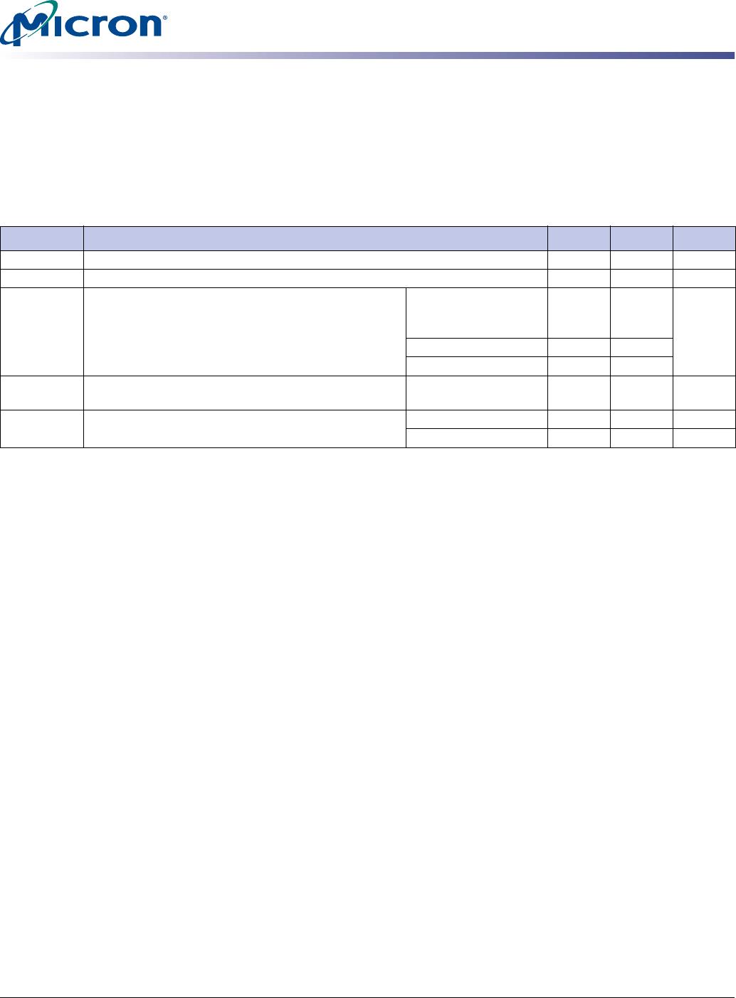
The MT8VDDT3264H and MT8VDDT6464H are high-speed, CMOS dynamic random
access 256MB and 512MB memory modules organized in a x64 configuration. These
modules use DDR SDRAM devices with four internal banks.
DDR SDRAM modules use a double data rate architecture to achieve high-speed opera-
tion. The double data rate architecture is essentially a 2n-prefetch architecture with an
interface designed to transfer two data words per clock cycle at the I/O pins. A single
read or write access for DDR SDRAM modules effectively consists of a single
2n-bit-wide, one-clock-cycle data transfer at the internal DRAM core and two corre-
sponding n-bit-wide, one-half-clock-cycle data transfers at the I/O pins.
A bidirectional data strobe (DQS) is transmitted externally, along with data, for use in
data capture at the receiver. DQS is a strobe transmitted by the DDR SDRAM during
READs and by the memory controller during WRITEs. DQS is edge-aligned with data for
READs and center-aligned with data for WRITEs.
DDR SDRAM modules operate from differential clock inputs (CK and CK#); the crossing
of CK going HIGH and CK# going LOW will be referred to as the positive edge of CK.
Commands are registered at every positive edge of CK. Input data is registered on both
edges of DQS, and output data is referenced to both edges of DQS, as well as to both
edges of CK.
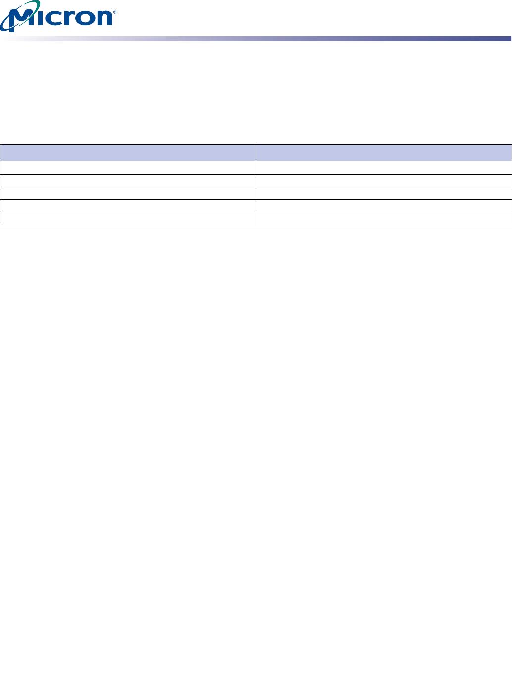
Serial Presence-Detect Operation
DDR SDRAM modules incorporate serial presence-detect. The SPD data is stored in a
256-byte EEPROM. The first 128 bytes are programmed by Micron to identify the module
type and various DDR SDRAM organizations and timing parameters. The remaining 128
bytes of storage are available for use by the customer. System READ/WRITE operations
between the master (system logic) and the slave EEPROM device occur via a standard
I
2
C bus using the DIMM’s SCL (clock) and SDA (data) signals, together with SA[2:0],
which provide eight unique DIMM/EEPROM addresses. Write protect (WP) is connected
to V
SS, permanently disabling hardware write protect.
PDF: 09005aef8092973f / Source: 09005aef80921669 Micron Technology, Inc., reserves the right to change products or specifications without notice.
DD8C32_64x64H.fm - Rev. D 9/08 EN
8 ©2004 Micron Technology, Inc. All rights reserved.
256MB, 512MB (x64, SR) 200-Pin DDR SDRAM SODIMM
Electrical Specifications
Stresses greater than those listed in Table 7 may cause permanent damage to the
module. This is a stress rating only, and functional operation of the module at these or
any other conditions outside those indicated on the device data sheet is not implied.
Exposure to absolute maximum rating conditions for extended periods may adversely
affect reliability.
Notes: 1. For further information, refer to technical note TN-00-08: “Thermal Applications,” available
on Micron’s Web site.
Table 7: Absolute Maximum Ratings
Symbol Parameter Min Max Units
V
DD/VDDQ
VDD/VDDQ supply voltage relative to VSS
–1.0 +3.6 V
V
IN, VOUT
Voltage on any pin relative to VSS
–0.5 +3.2 V
I
I
Input leakage current; Any input 0V VIN VDD;
V
REF input 0V VIN 1.35V (All other pins not under
test = 0V)
Address inputs,
RAS#, CAS#, WE#, BA,
S#, CKE
–16 +16 µA
CK, CK#
–8 +8
DM
–2 +2
IOZ
Output leakage current; 0V VOUT VDDQ; DQ are
disabled
DQ, DQS
–5 +5 µA
T
A
DRAM ambient operating temperature
1
Commercial
0+70°C
Industrial
–40 +85 °C
PDF: 09005aef8092973f / Source: 09005aef80921669 Micron Technology, Inc., reserves the right to change products or specifications without notice.
DD8C32_64x64H.fm - Rev. D 9/08 EN
9 ©2004 Micron Technology, Inc. All rights reserved.
256MB, 512MB (x64, SR) 200-Pin DDR SDRAM SODIMM
Electrical Specifications
DRAM Operating Conditions
Recommended AC operating conditions are given in the DDR component data sheets.
Component specifications are available on Microns Web site. Module speed grades
correlate with component speed grades, as shown in Table 8.
Design Considerations
Simulations
Micron memory modules are designed to optimize signal integrity through carefully
designed terminations, controlled board impedances, routing topologies, trace length
matching, and decoupling. However, good signal integrity starts at the system level.
Micron encourages designers to simulate the signal characteristics of the systems
memory bus to ensure adequate signal integrity of the entire memory system.
Power
Operating voltages are specified at the DRAM, not at the edge connector of the module.
Designers must account for any system voltage drops at anticipated power levels to
ensure the required supply voltage is maintained.
Table 8: Module and Component Speed Grades
DDR components may exceed the listed module speed grades
Module Speed Grade Component Speed Grade
-40B -5B
-335 -6
-262 -75E
-26A -75Z
-265 -75

MT8VDDT6464HY-335J1

Mfr. #:
Manufacturer:
Micron
Description:
MODULE DDR SDRAM 512MB 200SODIMM
Lifecycle:
New from this manufacturer.
Delivery:
DHL FedEx Ups TNT EMS
Payment:
T/T Paypal Visa MoneyGram Western Union