SSL21081T All information provided in this document is subject to legal disclaimers. © NXP B.V. 2013. All rights reserved.
Product data sheet Rev. 6 — 3 October 2013 13 of 22
NXP Semiconductors
SSL21081T
Compact non-dimmable LED driver IC
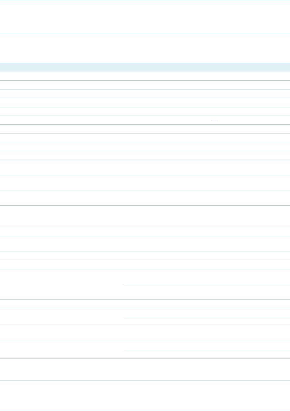
9. Limiting values
[1] The current into the VCC pin must not exceed the maximum I
DD
value.
[2] An internal clamp sets the supply voltage.
[3] Human body model: equivalent to discharging a 100 pF capacitor through a 1.5 k series resistor.
[4]
Charged device model: equivalent to charging the IC up to 1 kV and the subsequent discharging of each
pin down to 0 V over a 1 resistor.
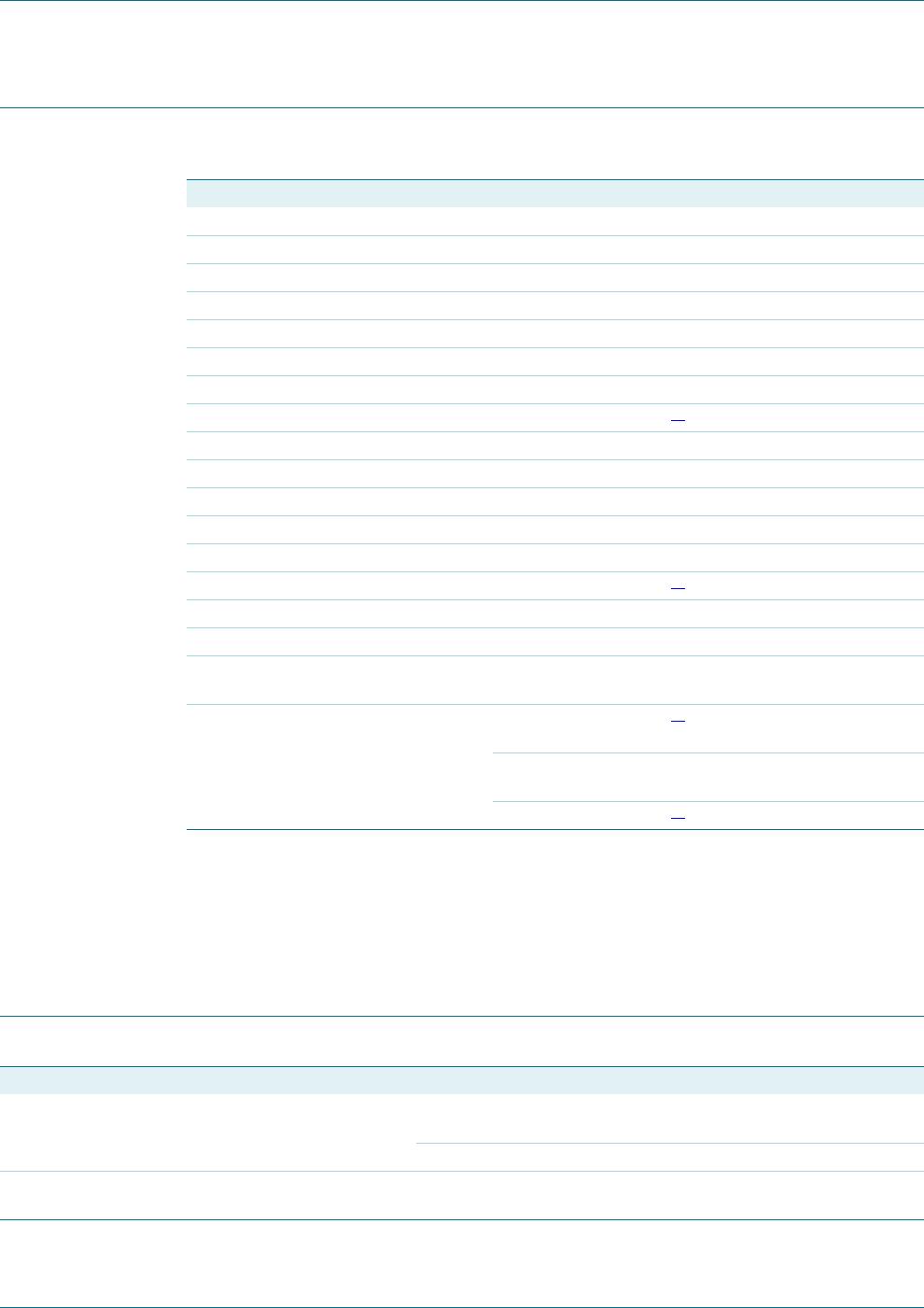
10. Thermal characteristics
Table 5. Limiting values
In accordance with the Absolute Maximum Rating System (IEC 60134).
Symbol Parameter Conditions Min Max Unit
General
SR slew rate on pin DRAIN 5 +5 V/ns
P
tot
total power dissipation SO8 package - 0.6 W
T
amb
ambient temperature 40 +125 C
T
j
junction temperature 40 +150 C
T
stg
storage temperature 55 +150 C
Voltages
V
CC
supply voltage continuous
[1]
0.4 +20 V
V
DRAIN
voltage on pin DRAIN 0.4 +300 V
V
HV
voltage on pin HV current limited 0.4 +300 V
V
SOURCE
voltage on pin SOURCE current limited 0.4 +5.2 V
V
NTC
voltage on pin NTC current limited 0.4 +5.2 V
Currents
I
DD
supply current at pin VCC
[2]
- 20 mA
I
DRAIN
current on pin DRAIN 2 +2 A
I
SOURCE
current on pin SOURCE 2 +2 A
I
DVDT
current on pin DVDT duration 20 s
maximum
- 1.3 A
V
ESD
electrostatic discharge
voltage
human body model;
pins DRAIN and HV
[3]
1 +1 kV
human body model;
all oth
er pins
2 +2 kV
charged device
[4]
500 +500 V
Table 6. Thermal characteristics
Symbol Parameter Conditions Typ Unit
R
th(j-a)
thermal resistance from junction to ambient in free air; SO8 package, PCB: 2 cm 3 cm,
2-layer, 35 m Cu per layer
142 K/W
in free air; SO8 package; PCB: JEDEC 2s2p 72 K/W
j-top
thermal characterization parameter from
junction to top of package
top package temperature measured at the
warmest point on top of the case; SO8 package
3.4 K/W