SSL21081T All information provided in this document is subject to legal disclaimers. © NXP B.V. 2013. All rights reserved.
Product data sheet Rev. 6 — 3 October 2013 4 of 22
NXP Semiconductors
SSL21081T
Compact non-dimmable LED driver IC
6. Block diagram
Fig 1. SSL21081T block diagram
DDD
-)(7
+
9
9&&
17&
*1'
'9'7
'5$,1
6285&(
9
6833/<
,17(51$/
5(*8/$725
$1'
%$1'*$3
G9GW
6833/<
9$//(<
'(7(&7,21
72))0$;
/2*,&
7210$;
%/$1.
/2*,&
&21752/
$1'
3527(&7,21
17&
)81&7,21
7+(50$/
6+87'2:1
325
9!9

SSL21081T All information provided in this document is subject to legal disclaimers. © NXP B.V. 2013. All rights reserved.
Product data sheet Rev. 6 — 3 October 2013 5 of 22
NXP Semiconductors
SSL21081T
Compact non-dimmable LED driver IC
7. Pinning information
7.1 Pinning
7.2 Pin description
Fig 2. SSL21081T pin configuration (SO8)
,&
+9
'5$,1
6285&( *1'
9&&
*1'
17&
'9'7
DDQ
Table 4. Pin description
Symbol Pin (SO8) Description
HV 1 high-voltage supply pin
SOURCE 2 low-side internal switch
VCC 3 supply voltage
NTC 4 LED temperature protection input
DVDT 5 AC supply pin
GND 6, 7 ground
DRAIN 8 high-side internal switch
SSL21081T All information provided in this document is subject to legal disclaimers. © NXP B.V. 2013. All rights reserved.
Product data sheet Rev. 6 — 3 October 2013 6 of 22
NXP Semiconductors
SSL21081T
Compact non-dimmable LED driver IC
8. Functional description
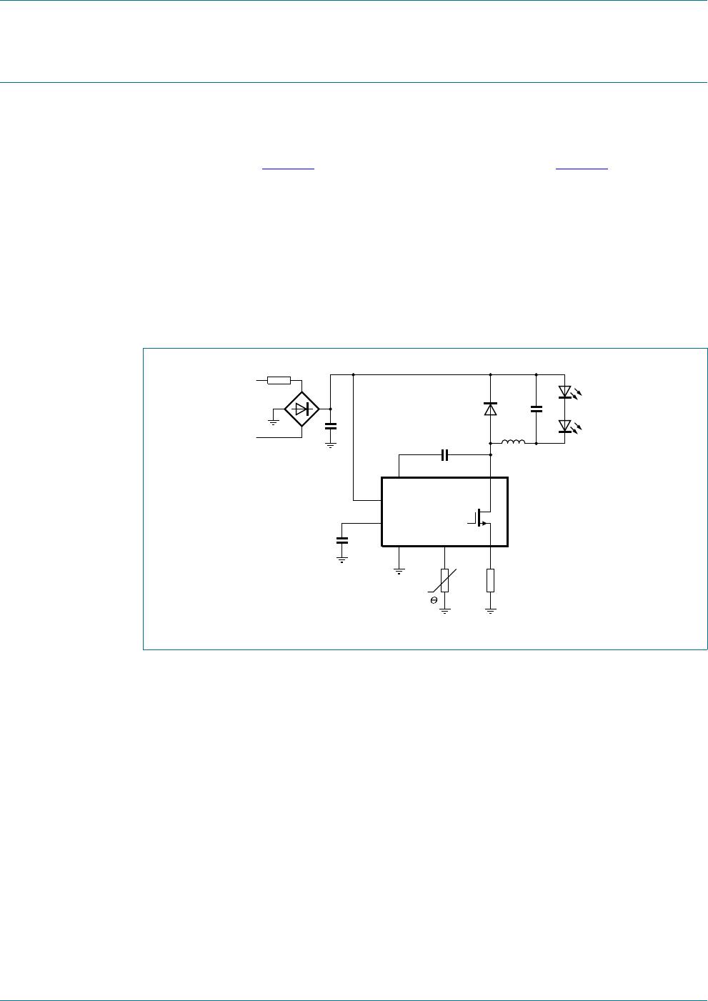
8.1 Converter operation
The converter in the SSL21081T is a Boundary Conduction Mode (BCM), peak current
controlled system. Figure
3 shows the basic application diagram. Figure 4 shows the
waveforms. This converter type operates at the boundary between continuous and
di
scontinuous mode. Energy is stored in inductor L each period that the switch is on. The
inductor current I
L
is zero when the internal MOSFET switch is switched on. Thereafter,
the amplitude of the current build-up in L is proportional to V
IN
V
OUT
and the time that
the internal MOSFET switch is on. When the internal MOSFET switch is switched off, the
current continues to flow through the freewheel diode and the output capacitor. The
current then falls at a rate proportional to the value of V
OUT
. The LED current I
LED
is
almost equal to half the peak switch current. As soon as the inductor current I
L
is zero, a
new cycle is started.
Fig 3. Basic SSL21081T application diagram
DDQ
5
LQUXVK

17&

*1' 6285&(
17& 5
VHQVH
/
'9'7 '5$,1
9
VHF
/('V
+9
9&&
,&

SSL21081T/1,118

Mfr. #:
Manufacturer:
NXP Semiconductors
Description:
LED Lighting Drivers Compact non-dimmable LED drive
Lifecycle:
New from this manufacturer.
Delivery:
DHL FedEx Ups TNT EMS
Payment:
T/T Paypal Visa MoneyGram Western Union

Products related to this Datasheet