SSL21081T All information provided in this document is subject to legal disclaimers. © NXP B.V. 2013. All rights reserved.
Product data sheet Rev. 6 — 3 October 2013 8 of 22
NXP Semiconductors
SSL21081T
Compact non-dimmable LED driver IC
8.3 Protective features
The IC has the following protective features:
• UnderVoltage LockOut (UVLO)
• Leading-Edge Blanking (LEB)
• OverCurrent Protection (OCP)
• Internal OverTemperature Protection (OTP)
• Brownout protection
• Short-Winding Protection (SWP)
• Output Short Protection (OSP)
• LED overtemperature control and protection
The SWP and the OSP are latched protections. These pr
otections cause the IC to halt
until a reset (a result of power cycling) is executed. When V
CC
drops to below V
CC(rst)
, the
IC resets the latch protection mode. The internal OTP and LED over temperature
protections are safe-restart protections. The IC halts, causing V
CC
to drop to below
V
CC(stop)
, triggering a start-up. When V
CC
drops to below V
CC(rst)
, the IC resets the latch
protection mode. Switching starts only when a no fault condition exists.
8.3.1 UnderVoltage LockOut (UVLO)
When the voltage on the VCC pin drops to below V
CC(stop)
, the IC stops switching. An
attempt is made to restart by supplying V
CC
from the HV pin voltage.
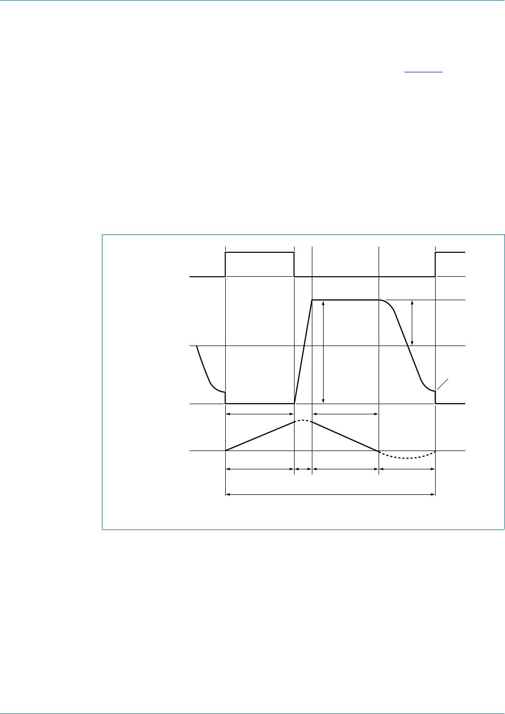
8.3.2 Leading-Edge Blanking (LEB)
To prevent false detection of the short-winding or overcurrent, a blanking time following
switch-on is implemented. When the internal MOSFET switch switches on, there can be a
short current spike due to capacitive discharge of voltage over the drain and source and
the charging of the gate to source capacitance. During the LEB time (t
leb
), the spike is
disregarded.
8.3.3 OverCurrent Protection (OCP)
The SSL21081T contain a highly accurate built-in peak current detector. It triggers when
the voltage at the SOURCE pin reaches the peak-level V
th(ocp)SOURCE
. The current
through the switch is sensed using a resistor connected to the SOURCE pin. The sense
circuit is activated following LEB time t
leb
. As the LED current is half the peak current (by
design), it automatically provides protection for maximum LED current during operation.
There is a propagation delay (t
d(ocp-swoff)
) between the overcurrent detection and the
actual switching off of the switch. Due to the delay, the actual peak current is slightly
higher than the OCP level set by the resistor in series to the SOURCE pin.
8.3.4 OverTemperature Protection (OTP)
When the internal OTP function is triggered at a certain IC temperature (T
th(act)otp
), the
converter stops operating. The safe-restart protection is triggered and the IC restarts with
switching resuming when the IC temperature drops lower than T
th(rel)otp
.