MAX9000–MAX9005
antenna can be long parallel wires spaced about 7.2cm
apart, with equal but opposite currents. Radio waves
from this antenna are detectable when the receiver is
brought within close proximity, but cancel out at greater
distances.
Infrared Receiver Front End for
Remote Controls and Data Links
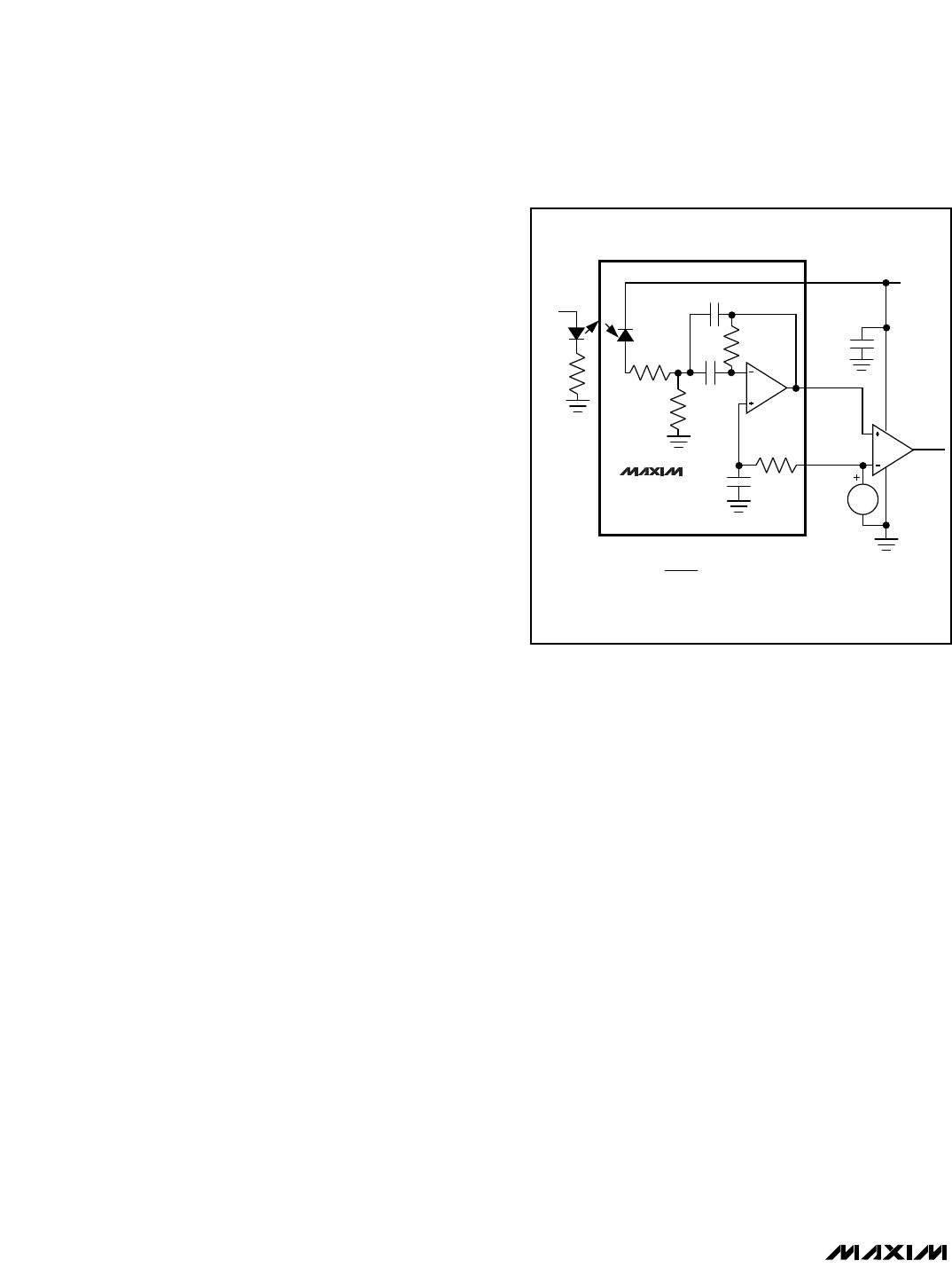
The circuit in Figure 9 uses the MAX9003 as a PIN pho-
todiode preamplifier and discriminator for an infrared
receiver. The op amp is configured as a Delyiannis-
noise and eliminates low-frequency interference from
sunlight, fluorescent lights, etc. This circuit is applica-
ble for TV remote controls and low-frequency data links
up to 200kbps. Carrier frequencies are limited to
around 100kHz, as in the example circuit. Component
layout and routing for the amplifier should be tight to
reduce stray capacitance, 60Hz interference, and RFI
from the comparator. Crosstalk from comparator edges
distorts the amplifier signal. To minimize this effect, add
a lowpass RC filter to the connection from the reference
to the op amp’s noninverting input.
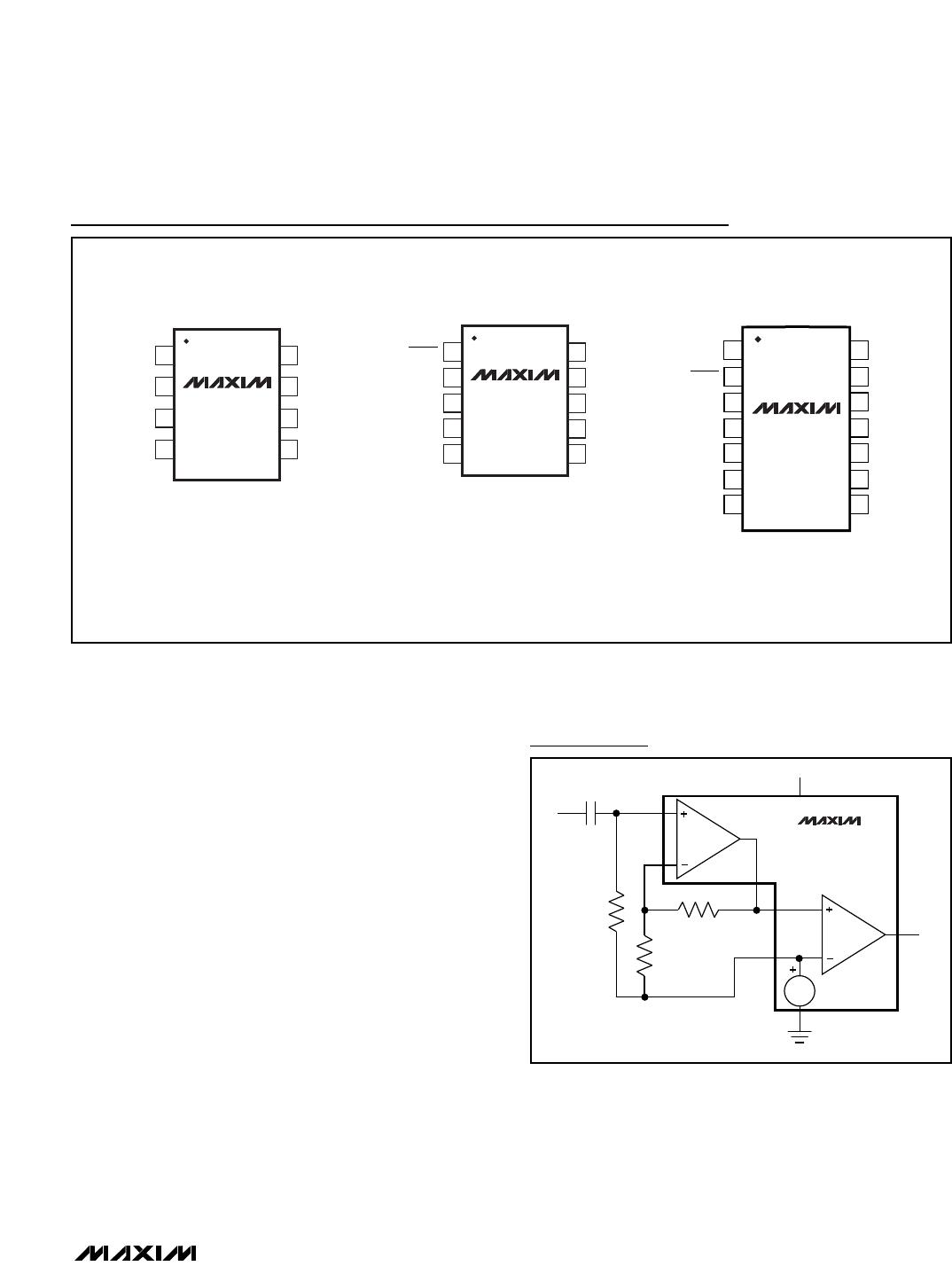
Signal Conditioning
For incoming signals that require filtering, the internal
amplifier provides an opportunity to create an active fil-
ter. This may be required for relatively high-speed sig-
nals that require adequate filtering of high-speed
carrier frequencies, harmonics, and external noise. In
addition, the amplifier can be used to amplify the signal
prior to digitizing it through the comparator to improve
the comparator’s overall output response and improve
its noise immunity.
Low-Power, High-Speed, Single-Supply
Op Amp + Comparator + Reference ICs
16 ______________________________________________________________________________________
REF
0.1µF
0.1µF
1
2π f
C
100k
1.230V
V
CC
= 5V
COMP
AMP
C2
15pF, 5%
100kHz,
5Vp-p
C1
150pF,
5%
NEC
PH302B
NEC
SE307-C
51
R1
A
49.9k
1%
R1
B
4.99k
1%
R2
100k,
1%
LAYOUT-SENSITIVE AREA
MAX9003
R1 x C1 = R2 x C2 =
4.99k
Figure 9. Infrared Receiver Application
MAX9000–MAX9005
Low-Power, High-Speed, Single-Supply
Op Amp + Comparator + Reference ICs
______________________________________________________________________________________ 17
Pin Configurations
CIN+
REF (CIN-)V
SS
( ) ARE FOR THE MAX9002/MAX9005.
1
2
8
7
V
DD
COUTAIN-
AIN+
AOUT
SO/µMAX
TOP VIEW
3
4
6
5
MAX9000
MAX9002
MAX9003
MAX9005
1
2
3
4
5
10
9
8
7
6
V
DD
COUT
CIN+
CIN-AIN+
AIN-
AOUT
SHDN
MAX9001
MAX9004
µMAX
SO
REFV
SS
14
13
12
11
10
9
8
1
2
3
4
5
6
7
N.C.
V
DD
COUT
CIN+AIN-
AOUT
SHDN
N.C.
MAX9001
MAX9004
CIN-
REF
N.C.N.C.
V
SS
AIN+
AIN+
INPUT
AIN-
OP AMP
COMP
REF
CIN+
AOUT
REF
0.1µF
1.230V
V
SS
V
DD
R1
R2
1M
COUT
MAX9000
MAX9003
Typical Operating Circuit
MAX9000–MAX9005
Low-Power, High-Speed, Single-Supply
Op Amp + Comparator + Reference ICs
18 ______________________________________________________________________________________
Ordering Information (continued) Chip Information
TRANSISTOR COUNT: 283
PART TEMP. RANGE PIN-PACKAGE
MAX9002EUA
MAX9002ESA -40°C to +85°C
-40°C to +85°C 8 µMAX
8 SO
MAX9003EUA
MAX9003ESA
MAX9004EUB
MAX9004ESD
-40°C to +85°C
-40°C to +85°C 8 µMAX
8 SO
-40°C to +85°C
-40°C to +85°C 10 µMAX
14 SO
MAX9005EUA
MAX9005ESA -40°C to +85°C
-40°C to +85°C 8 µMAX
8 SO
Package Information
8LUMAXD.EPS

MAX9005EUA+T

Mfr. #:
Manufacturer:
Maxim Integrated
Description:
High Speed Operational Amplifiers Op Amp Comparator Reference IC
Lifecycle:
New from this manufacturer.
Delivery:
DHL FedEx Ups TNT EMS
Payment:
T/T Paypal Visa MoneyGram Western Union