BATTERY PROTECTION IC FOR 1-SERIAL TO 4-SERIAL-CELL PACK (SECONDARY PROTECTION)
S-8244 Series
Rev.6.1_00
Seiko Instruments Inc.
10
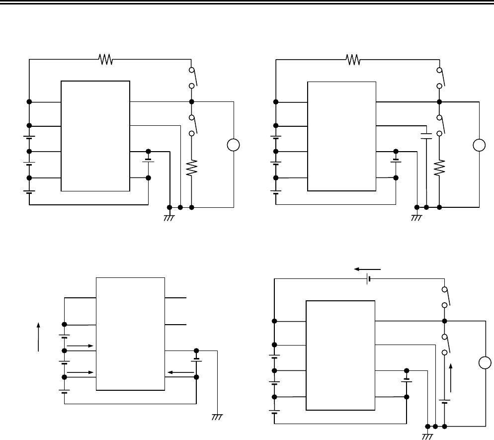
(4) Test Condition 4, Test Circuit 1
Set switches 1 and 2 to OFF for CMOS output product.
Set switch 1 to ON and switch 2 to OFF for Nch open drain product.
Set switch 1 to OFF and switch 2 to ON for Pch open drain product.
• Product with CMOS output active “H”, Nch open drain output active “H”
The overcharge detection voltage 4 (V
CU4
) is a voltage at V4; when the CO pin’s voltage is set to “H” by increasing
V4 gradually, after setting V1 = V2 = V3 = V4 = 3.5 V. After that, gradually decreasing V4’s voltage to set CO = “L”,
and the difference of this V4’s voltage and V
CU4
is the overcharge hysteresis voltage 4 (V
CD4
).
• Product with CMOS output active “L”, Nch open drain output active “L”, Pch open drain output active “L”
The overcharge detection voltage 4 (V
CU4
) is a voltage at V4; when the CO pin’s voltage is set to “L” by increasing
V4 gradually, after setting V1 = V2 = V3 = V4 = 3.5 V. After that, gradually decreasing V4’s voltage to set CO =
“H”, and the difference of this V4’s voltage and V
CU4
is the overcharge hysteresis voltage 4 (V
CD4
).
(5) Test Condition 5, Test Circuit 2
Set switches 1 and 2 to OFF for CMOS output product.
Set switch 1 to ON and switch 2 to OFF for Nch open drain product.
Set switch 1 to OFF and switch 2 to ON for Pch open drain product.
• Product with CMOS output active “H”, Nch open drain output active “H”
Rise V1 to 4.7 V momentarily within 10
μs after setting V1 = V2 = V3 = V4 = 3.5 V. The period from V1 having
reached 4.7 V to CO = “H” is the overcharge detection delay time (t
CU
).
• Product with CMOS output active “L”, Nch open drain output active “L”, Pch open drain output active “L”
Rise V1 to 4.7 V momentarily within 10
μs after setting V1 = V2 = V3 = V4 = 3.5 V. The period from V1 having
reached 4.7 V to CO = “L” is the overcharge detection delay time (t
CU
).
(6) Test Condition 6, Test Circuit 3
Measure current consumption (I1) setting V1 = V2 = V3 = V4 = 2.3 V. This I1 is current consumption at power-down
(I
PDN
).
Measure current consumption (I1) setting V1 = V2 = V3 = V4 = 3.5 V. This I1 is current consumption during normal
operation (I
OPE
), I2 is the VC1 sink current (I
VC1
), I3 is the VC2 sink current (I
VC2
), I4 is the VC3 sink current (I
VC3
).