BATTERY PROTECTION IC FOR 1-SERIAL TO 4-SERIAL-CELL PACK (SECONDARY PROTECTION)
Rev.6.1_00
S-8244 Series
Seiko Instruments Inc.
19
Precautions
• This IC charges the delay capacitor through the delay capacitor pin (ICT pin) immediately when the voltage of one of
batteries V1 to V4 reaches the overcharge voltage. Therefore, setting the resistor connected to the VCC pin to any
value greater than the recommended level causes a reduction in the IC power supply voltage because of charge
current of the delay capacitor. This may lead to a malfunction. Set up the resistor NOT to exceed the typical value.
If you change the resistance, please consult us.
• DO NOT connect any of overcharged batteries. Even if only one overcharged battery is connected to this IC, the IC
detects overcharge, then charge current flows to the delay capacitor through the parasitic diode between pins where
the battery is not connected yet. This may lead to a malfunction. Please perform sufficient evaluation in the case of
use. Depending on an application circuit, even when the fault charge battery is not contained, the connection turn of
a battery may be restricted in order to prevent the output of CO detection pulse at the time of battery connection.
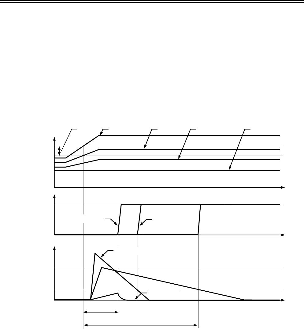
V
CU
Battery voltage
Setting voltage
V
CC
CO pin voltage
V
SS
V
SS
ICT pin voltage
CMOS output active “H” and Nch open drain output active “H” products
V
CD
V1 battery V2 battery V3 battery V4 battery
Internal delay
Delay
C
ICT
low
C
ICT
high
C
ICT
low
C
ICT
high
V
SS
• In this IC, the output logic of the CO pin is inverted after several milliseconds of internal delay if this IC is under the
overcharge condition even ICT pin is either “V
SS
−short circuit,” “V
DD
−short circuit” or “Open” status.
• Any position from V1 to V4 can be used when applying this IC for a one to three-cell battery. However, be sure to
short circuit between pins not in use (SENSE
−VC1, VC1−VC2, VC2−VC3, or VC3−VSS).
• The application conditions for the input voltage, output voltage, and load current should not exceed the package
power dissipation.
• Do not apply an electrostatic discharge to this IC that exceeds the performance ratings of the built-in electrostatic
protection circuit.
• SII claims no responsibility for any and all disputes arising out of or in connection with any infringement of the
products including this IC upon patents owned by a third party.