BATTERY PROTECTION IC FOR 1-SERIAL TO 4-SERIAL-CELL PACK (SECONDARY PROTECTION)
Rev.6.1_00
S-8244 Series
Seiko Instruments Inc.
13
Operation
Remark Refer to “ Battery Protection IC Connection Example”.
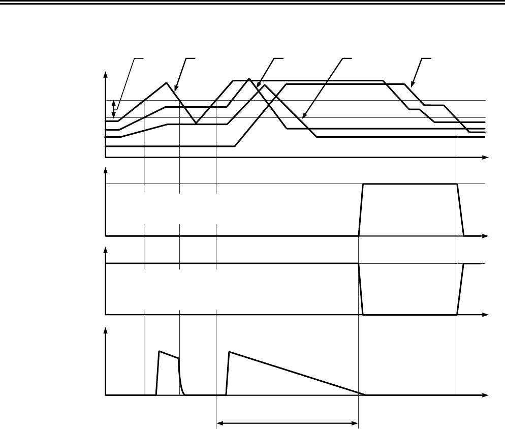
1. Overcharge Detection
•
Product with CMOS output active “H”, Nch open drain output active “H”
During charging in the normal status, any of battery voltages exceeds overcharge detection voltage (V
CU
), and this
status is maintained for overcharge detection delay time (t
CU
) or longer, CO gets “H”. This is overcharge status.
Connecting an FET to the CO pin enables charge-control and the second protect.
In this case, the IC maintains the overcharge status until all battery voltages decreases, to the overcharge
hysteresis voltage (V
CD
) from the overcharge detection voltage (V
CU
).
• Product with CMOS output active “L”, Nch open drain output active “L”, Pch open drain output active “L”
During charging in the normal status, any of battery voltages exceeds overcharge detection voltage (V
CU
), and this
status is maintained for overcharge detection delay time (t
CU
) or longer, CO gets “L”. This is overcharge status.
Connecting an FET to the CO pin enables charge-control and the second protect.
In this case, the IC maintains the overcharge status until all battery voltages decreases, to the overcharge
hysteresis voltage (V
CD
) from the overcharge detection voltage (V
CU
).
2. Delay Circuit
The delay circuit rapidly charges the capacitor connected to the delay capacitor connection pin up to a specified
voltage when the voltage of one of the batteries exceeds the overcharge detection voltage (V
CU
). Then, the delay
circuit gradually discharges the capacitor at 100 nA and inverts the CO output when the voltage at the delay
capacitor connection pin goes below a specified level. Overcharge detection delay time (t
CU
) varies depending
upon the external capacitor.
Each delay time is calculated using the following equation.
Min. Typ. Max.
t
CU
[s] = Delay Coefficient (10, 15, 20) × C
ICT
[μF]
Because the delay capacitor is rapidly charged, the smaller the capacitance, the larger the difference between the
maximum voltage and the specified value of delay capacitor pin (ICT pin). This will cause a deviation between the
calculated delay time and the resultant delay time. Also, delay time is internally set in this IC to prevent the CO
output from inverting until the charge to delay capacitor pin is reached to the specified voltage. If large
capacitance is used, output may be enabled without delay time because charge is disabled within the internal delay
time.
Please note that the maximum capacitance connected to the delay capacitor pin (ICT pin) is 1
μF.