LTC3626
13
3626fa
For more information www.linear.com/LTC3626
applicaTions inForMaTion
A general LTC3626 application circuit is shown on the first
page of this data sheet. External component selection is
largely driven by the load requirement and begins with the
selection of the inductor L. Once the inductor is chosen,
the input capacitor, C
IN
, the output capacitor, C
OUT
, the
internal regulator capacitor, C
INTVCC
, and the boost capaci-
tor, C
BST
, can be selected. Next, the feedback resistors
are selected to set the desired output voltage. Finally, the
remaining optional external components can be selected
for functions such as external loop compensation, PGOOD,
average output current monitor and limit, average input
current monitor and limit, and on-die temperature moni
-
tor and limit.
Operating Frequency
Selection of the operating frequency is a trade-off between
efficiency and component size. High frequency operation
allows the use of smaller inductor and capacitor values.
Operation at lower frequencies improves efficiency by
reducing internal gate charge losses but requires larger
inductance values and/or capacitance to maintain low
output ripple voltage.
The operating frequency, f, of the LTC3626 is determined
by an external resistor that is connected between the RT
pin and ground. The value of the resistor sets the ramp
current that is used to charge and discharge an internal
timing capacitor within the oscillator and can be calculated
by using the following equation:
R
RT
=
3.2E11
f
where R
RT
is in Ω and f is in Hz.
Connecting the RT pin to INTV
CC
will assert the internal
default frequency f = 2MHz; however, this switching fre-
quency will be more sensitive to process and temperature
variations than using a resistor on R
T
(see Typical Perfor-
mance Characteristics).
The LTC
3626
is not optimized for constant on-time opera-
tion when configured to generate output voltages greater
than 6V. Though output regulation will be maintained under
this condition
, it is possible the operating frequency may be
higher than the programmed value. As a result, for output
Figure 1. Switching Frequency vs R
T
voltages greater than 6V, the value of the R
T
resistor may
need adjustment to obtain the desired operating frequency.
Inductor Selection
For a given input and output voltage, the inductor value and
operating frequency determine the inductor ripple current.
More specifically, the inductor ripple current decreases
with higher inductor value or higher operating frequency
according to the following equation:
I
L
=
V
OUT
f L
1
V
OUT
V
IN
where ΔI
L
= inductor ripple current, V
IN
= PV
IN
, f = operat-
ing frequency and L =
inductor value. A trade-off between
component size, efficiency and operating frequency can
be seen from this equation. Accepting larger values of
ΔI
L
allows the use of lower value inductors but results
in greater core loss in the inductor, greater ESR loss in
the output capacitor, and larger output ripple. Generally,
highest efficiency operation is obtained at low operating
frequency with small ripple current.
A reasonable starting point for setting the ripple current
is approximately 1A
P-P
. Note that the largest ripple cur-
rent occurs at the highest V
IN
. Further, the inductor ripple
current must not be so large that the trough or valley
reaches the negative valley current limit of –1A (typical)
when operating in forced continuous mode. If the inductor
current trough reaches the negative current limit while in
forced continuous mode operation, V
OUT
may exceed the
R
T
(kΩ)
0
2000
2500
3500
300 500
3626 F01
1500
1000
100 200
400 600 700
500
0
3000
FREQUENCY (kHz)
LTC3626
14
3626fa
For more information www.linear.com/LTC3626
applicaTions inForMaTion
target regulation voltage. To guarantee the ripple current
does not exceed a specified maximum the inductance
should be chosen according to:
L =
V
OUT
f I
L(MAX)
1
V
OUT
V
IN(MAX)
Once the value for L is known, the type of inductor must
be selected. Actual core loss is independent of core size
for a fixed inductor value but is very dependent on the
inductance selected. As the inductance increases, core loss
decreases. Unfortunately, increased inductance requires
more turns of wire leading to increased copper loss.
Ferrite designs exhibit very low core loss and are preferred
at high switching frequencies, so design goals can con
-
centrate on copper loss and preventing saturation. Ferrite
core materials saturate
“hard,”
meaning the inductance
collapses abruptly when the peak design current is ex
-
ceeded. This collapse will result in an abrupt increase in
inductor ripple current, so it is important to ensure the
core will not saturate.
Different core materials and shapes will change the size/
current and price/current relationship of an inductor.
Toroidal or shielded pot cores in ferrite or permalloy
materials are small and dont radiate much energy but
generally cost more than powdered iron core inductors
with similar characteristics. The choice of which style
inductor to use mainly depends on the price versus size
requirements and any radiated field/EMI requirements.
New designs for surface mount inductors are available
from Toko, Vishay, NEC/Tokin, Cooper, Coilcraft, TDK and
rth Elektronik. Table 1 gives a sampling of available
surface mount inductors.
C
IN
and C
OUT
Selection
The input capacitance, C
IN
, is needed to filter the trapezoi-
dal wave current at the drain of the top power MOSFET.
To prevent large voltage transients from occurring
, a low
ESR input capacitor sized for the maximum RMS current
is recommended. The maximum RMS current is given by:
I
RMS
=I
OUT(MAX)
V
OUT
V
IN
V
OUT
( )
V
IN
This formula has a maximum at V
IN
= 2V
OUT
, where
I
RMS
I
OUT
/2. This simple worst-case condition is com-
monly used for design because even significant deviations
do not offer much relief.
Note that ripple current ratings
Table 1. Inductor Selection Table
INDUCTANCE DCR MAX CURRENT DIMENSIONS HEIGHT
Vishay IHLP-2525CZ-01 Series
0.33µH 3.5mW 20A 6.5mm × 7mm 3mm
0.47µH 4.0mW 17.5A
0.68µH 5.0mW 15.5A
0.82µH 6.7mW 13A
1.0µH 9.0mW 11A
1.5µH 14mΩ 9A
2.2µH 18mΩ 8A
3.3µH 28mΩ 6A
4.7µH 37mΩ 5.5A
6.8µH 54mΩ 4.5A
Toko FDV0620 Series
0.47µH 8.3mW 9A 7mm × 7.7mm 2.0mm
1µH 18.3mW 5.7A
NEC/Tokin MLC0730L Series
0.47µH 4.5mW 16.6A 6.9mm × 7.7mm 3.0mm
0.75µH 7.5mW 12.2A
1µH 9mW 10.6A
Cooper HCP0703 Series
0.47µH 4.2mW 17A 7mm × 7.3mm 3.0mm
0.68µH 5.5mW 15A
0.82µH 8mW 13A
1µH 10mW 11A
1.5µH 14mW 9A
TDK RLF7030 Series
1µH 8.8mW 6.4A 6.9mm × 7.3mm 3.2mm
1.5µH 9.6mW 6.1A
2.2µH 12mW 5.4A
Würth Elektronik WE-HC 744312 Series
0.47µH 3.4mW 16A 7mm × 7.7mm 3.8mm
0.72µH 7.5mW 12A
1µH 9.5mW 11A
1.5µH 10.5mW 9A
LTC3626
15
3626fa
For more information www.linear.com/LTC3626
applicaTions inForMaTion
from capacitor manufacturers are often based on only
2000 hours of life which makes it advisable to further de-
rate the capacitor, or choose a capacitor rated at a higher
temperature than required.
Several capacitors may also be paralleled to meet size or
height requirements in the design. For low input voltage
applications, sufficient bulk input capacitance is needed
to minimize transient effects during output load changes.
Even though the LTC3626 design includes an overvoltage
protection circuit, care must always be taken to ensure
input voltage transients do not pose an overvoltage hazard
to the part.
Additional input voltage filtering to the SV
IN
pin (signal
V
IN
) is made possible by adding optional components R
IN
and C
IN2
as shown in the Functional Diagram. Generally,
the inherent supply rejection of the LTC3626 makes the
addition of these components unnecessary, however, users
with large, asynchronous noise on the input supply may
choose to populate these components. Typical values for
R
IN
and C
IN2
are 5Ω and 0.33µF respectively.
The selection of C
OUT
is determined by the effective series
resistance (ESR) that is required to minimize voltage ripple
and load step transients as well as the amount of bulk
capacitance that is necessary to ensure that the control
loop is stable. Loop stability can be checked by viewing
the load transient response. The output ripple, V
OUT
, is
approximated by:
V
OUT
< I
L
ESR+
1
8 f C
OUT
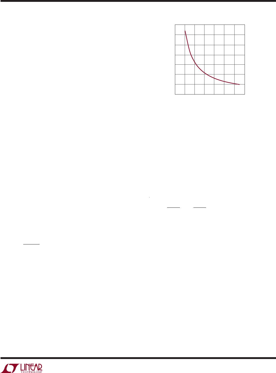
When using low ESR ceramic capacitors, it is more useful
to choose the output capacitor value to fulfill a charge stor-
age requirement. During a load step, the output capacitor
must instantaneously supply the current to support the load
until the feedback loop raises the switch current enough
to support the load
. The time required for the feedback
loop to respond is dependent on the compensation and the
output capacitor size. Typically, 3 to 4 cycles are required
to respond to a load step, but only in the first cycle does
the output drop linearly. The output droop, V
DROOP
, is
usually about 3 times the linear drop of the first cycle.
Thus, a good place to start is with the output capacitor
size of approximately:
C
OUT
3
I
OUT
f V
DROOP
Though this equation provides a good approximation, more
capacitance may be required depending on the duty cycle
and load step requirements. The actual V
DROOP
should be
verified by applying a load step to the output.
Using Ceramic Input and Output Capacitors
Higher value, lower cost ceramic capacitors are now
available in small case sizes. Their high voltage rating
and low ESR make them ideal for switching regulator ap
-
plications. However, due to the self-resonant and high-Q
characteristics of some types of ceramic capacitors,
care
must be taken when these capacitors are used at the input
and output. When a ceramic capacitor is used at the input,
and the power is supplied by a wall adapter through long
wires, a load step at the output can induce ringing at the
V
IN
input. At best, this ringing can couple to the output and
be mistaken as loop instability. At worst, a sudden inrush
of current through the long wires can potentially cause a
voltage spike at V
IN
large enough to damage the part. For
a more detailed discussion, refer to Application Note 88.
When choosing the input and output ceramic capacitors
choose the X5R or X7R dielectric formulations. These
dielectrics provide the best temperature and voltage
characteristics for a given value and size.
INTV
CC
Regulator
An internal low dropout (LDO) regulator produces a
3.3V supply voltage used to power much of the internal
LTC3626 circuitry including the power MOSFET gate
drivers. The INTV
CC
pin connects to the output of this
regulator and should have a minimum F of decoupling
capacitance to ground. The decoupling capacitor should
have low impedance electrical connections to the INTV
CC
and PGND pins to provide the transient currents required
by the LTC3626. The user may connect a maximum load
current of 5mA to this pin but must take into account the
increased power dissipation and die temperature that

LTC3626IUDC#PBF

Mfr. #:
Manufacturer:
Analog Devices / Linear Technology
Description:
Switching Voltage Regulators 3A, 20V Monolithic Step-Down Regulator with Current and Temperature Monitoring
Lifecycle:
New from this manufacturer.
Delivery:
DHL FedEx Ups TNT EMS
Payment:
T/T Paypal Visa MoneyGram Western Union