25AA040/25LC040/25C040
DS21204E-page 10 © 2006 Microchip Technology Inc.
3.5 Read Status Register (RDSR)
The RDSR instruction provides access to the STATUS
register. The STATUS register may be read at any time,
even during a write cycle. The STATUS register is
formatted as follows:
The Write-In-Process (WIP) bit indicates whether the
25XX040 is busy with a write operation. When set to a
‘
1’, a write is in progress, when set to a ‘0’, no write is
in progress. This bit is read-only.
The Write Enable Latch (WEL) bit indicates the status
of the write enable latch. When set to a ‘
1’, the latch
allows writes to the array, when set to a ‘
0’, the latch
prohibits writes to the array. The state of this bit can
always be updated via the WREN or WRDI commands
regardless of the state of write protection on the
STATUS register. This bit is read-only.
The Block Protection (BP0 and BP1) bits indicate
which blocks are currently write-protected. These bits
are set by the user issuing the WRSR instruction. These
bits are nonvolatile.
See Figure 3-6 for RDSR timing sequence.
3.6 Write Status Register (WRSR)
The WRSR instruction allows the user to select one of
four levels of protection for the array by writing to the
appropriate bits in the STATUS register. The array is
divided up into four segments. The user has the ability
to write-protect none, one, two, or all four of the
segments of the array. The partitioning is controlled as
illustrated in Table 3-2.
See Figure 3-7 for WRSR timing sequence.
TABLE 3-2: ARRAY PROTECTION
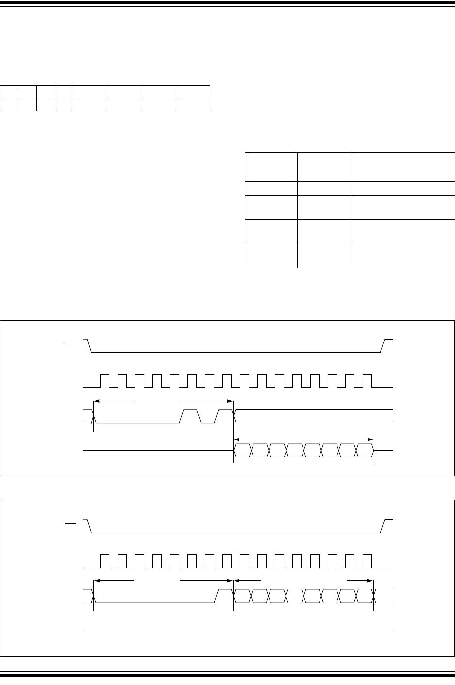
FIGURE 3-6: READ STATUS REGISTER SEQUENCE
FIGURE 3-7: WRITE STATUS REGISTER SEQUENCE
7654 3 2 1 0
XXXX BP1 BP0 WEL WIP
BP1 BP0
Array Addresses
Write-Protected
00
none
01
upper 1/4
(0180h-01FFh)
10
upper 1/2
(0100h-01FFh)
11
all
(0000h-01FFh)
SO
SI
CS
9101112131415
11000000
7654 210
Instruction
Data from STATUS register
High-impedance
SCK
0 2345671
8
3
SO
SI
CS
9101112131415
01000000
7654
210
Instruction Data to STATUS register
High-impedance
SCK
0 2345671
8
3