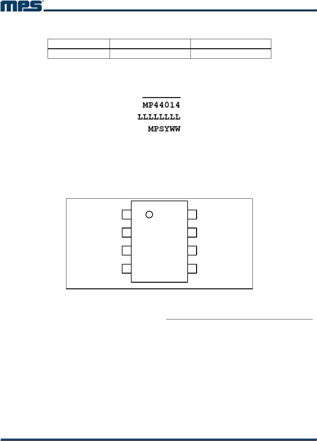
MP44014
Boundary Mode PFC Controller
MP44014 Rev. 1.01 www.MonolithicPower.com 1
11/10/2015 MPS Proprietary Information. Patent Protected. Unauthorized Photocopy and Duplication Prohibited.
© 2015 MPS. All Rights Reserved.
The Future of Analog IC Technology
DESCRIPTION
The MP44014 is a boundary conduction mode
PFC controller that provides simple, high-
performance, active power factor correction
using minimal external components.
The output voltage is regulated accurately by a
high-performance voltage mode amplifier with
an accurate internal voltage reference.
The precise, adjustable output over-voltage
protection greatly enhances system reliability.
The on-chip R/C filter on the current sense pin
can potentially eliminate the external R/C filter.
The extremely low start-up current, quiescent
current, and disable function reduces power
consumption, resulting in excellent efficiency
performance.
The MP44014 is available in a SOIC-8 package.
FEATURES
Boundary Conduction Mode PFC Controller
for Pre-Regulator
Zero-Crossing Compensation to Minimum
THD of the AC Input Current
Precise Adjustable Output Over-Voltage
Protection
Ultra-Low (15μA) Start-U p Current
Low Quiescent Current (0.46uA) at OVP
Condition
On-Chip Filter on Current Sense Pin
Disable Function on ZCS Pin
-750mA/+800mA Peak Gate Drive Current
Available in SOIC-8 Packages
APPLICATIONS
Offline Adaptors
Electronic Ballast
LLC Front End
Other PFC Pre-Regulators
All MPS parts are lead-free, halogen-free, and adhere to the RoHS directive. Fo
r
MPS green status, please visit the MPS website under Quality Assurance.
“MPS” and “The Future of Analog IC Technology” are registered trademarks o
f
Monolithic Power Systems, Inc.
Other patents pending.
TYPICAL APPLICATION
GATE
FB
CS
GND
COMP
ZCS
VCC
MULT
M44014
D1
C1
R1
R2
R3
D2
D3
C2
C3
C4
C5
C8
R4
R5
R6
R7
R8
R9
R11
Q1
L1
U1
C6
C7
R10
MP44014 – BOUNDARY MODE PFC CONTROLLER
MP44014 Rev. 1.01 www.MonolithicPower.com 2
11/10/2015 MPS Proprietary Information. Patent Protected. Unauthorized Photocopy and Duplication Prohibited.
© 2015 MPS. All Rights Reserved.
ORDERING INFORMATION
Part Number Package Top Marking
MP44014GS*
SOIC-8
See Below
* For Tape & Reel, add suffix –Z (e.g. MP44014GS–Z)
TOP MARKING
MP44014: Part number
LLLLLLLL: Lot number
MPS: MPS prefix
Y: Year code
WW: Week code
PACKAGE REFERENCE
1
2
3
45
6
7
8
FB
COMP
MULT
CS
ZCS
GND
GATE
VCC
ABSOLUTE MAXIMUM RATINGS
(1)
Supply voltage (VCC) .............. -0.5V to self limit
Analog inputs and outputs
(2)
..........-0.3V to 6.5V
ZCS max. current......................-2.5mA to 10mA
Continuous power dissipation (T
A
= +25°C)
(3)
SOIC-8....................................................... 1.4W
Junction temperature………………… …..150C
Lead temperature (solder) ........................260C
Storage temperature................ -55C to +150C
Recommended Operating Conditions
(4)
Supply voltage (VCC) ....................13.4V to 22V
Analog inputs and outputs .............-0.3V to 6.5V
Operating junction temp. (T
J
). .. -40°C to +125°C
Thermal Resistance
(5)
θ
JA
θ
JC
SOIC-8 ....................................90 ...... 45... C/W
NOTES:
1) Exceeding these ratings may damage the device.
2) Except ZCS pin, which is self limited.
3) The maximum allowable power dissipation is a function of the
maximum junction temperature T
J
(MAX), the junction-to-
ambient thermal resistance θ
JA
, and the ambient temperature
T
A
. The maximum allowable continuous power dissipation at
any ambient temperature is calculated by
D(MAX)=(T
J
(MAX)-T
A
)/θ
JA
. Exceeding the maximum
allowable power dissipation will produce an excessive die
temperature, causing the regulator to go into thermal
shutdown. Internal thermal shutdown circuitry protects the
device from permanent damage.
4) The device is not guaranteed to function outside of its
operating conditions.
5) Measured on JESD51-7, 4-layer PCB.
MP44014 – BOUNDARY MODE PFC CONTROLLER
MP44014 Rev. 1.01 www.MonolithicPower.com 3
11/10/2015 MPS Proprietary Information. Patent Protected. Unauthorized Photocopy and Duplication Prohibited.
© 2015 MPS. All Rights Reserved.
ELECTRICAL CHARACTERISTICS
V
CC
= 15V, C
GATE
= 1nF, T
J
= -40C~+125C, unless otherwise noted.
Parameter Symbol Condition Min Typ Max Units
Supply Voltage
Operating range V
CC
After turn on 10.7 21 V
Turn-on threshold V
CC_on
11 12.3 13.8 V
Turn-off threshold V
CC_off
8.7 9.8 10.8 V
Hysteresis V
CC_hys
2.1 3 V
Zener voltage V
z
I
IN
= 20mA 22 25 29 V
Supply Current
Start-up current I
startup
V
CC
= 11V 15 30 µA
Quiescent current I
q
No switch 2.5 3.2 mA
Operating current I
cc
F
s
= 70kHz,
C
LOAD
= 1nF
3.5 4.5 mA
Quiescent current I
q
During OVP (either
static or dynamic)
or V
FB
150mV
0.46 0.7 mA
Multiplier
Input bias current I
MULT
-1 µA
Linear operation range V
MULT
0 3 V
Output max. slope ΔV
CS
/ΔV
MULT
V
MULT
= 0~0.6V
V
COMP
= upper clamp
1.60 1.90 V/V
Gain
(6)
K
V
MULT
= 1V, V
COMP
= 4V,
T
J
= 25
o
C
0.5 0.6 0.7 1/V
Error Amplifier
Feedback voltage V
FB
T
J
= 25
o
C 2.465 2.5 2.535 V
Feedback voltage line regulation V
FB_LR
VCC = 10.7V to 22V 2 5 mV
Feedback bias current I
FB
V
FB
= 2.6V 1 µA
Source current I
COMP_source
V
COMP
= 4V, V
FB
= 2.4V,
T
J
= 25
o
C
-2.7 -4.7 -6.9 mA
Sink current I
COMP_sink
V
COMP
= 4V, V
FB
= 2.6V,
T
J
= 25
o
C
3 5 mA
Upper clamp voltage V
COMP_H
V
FB
= 2V, I
comp
= -0.5mA 5.5 6.1 6.5 V
Lower clamp voltage V
COMP_L
V
FB
= 2V, I
comp
= -0.5mA 2.0 2.15 2.3 V
Current Sense Comparator
Input bias current I
CS
CS = 0 -1 µA
Turn-off delay T
DT
MULT = 0.2V 190 ns
LEB time T
LEB
MULT = 0.2V 45 70 95 ns
Current sense clamp voltage V
CS_Clamp
1.6 1.72 1.83 V
V
MULT
= 0V 26 mV
Current sense offset V
CS_Offset
V
MULT
= 2.5V 8 mV
Zero Current Sensor
Upper clamp voltage V
ZCSclamp_H
I
ZCS
= 2.5mA 7.1 7.8 8.6 V

MP44014GS-Z

Mfr. #:
Manufacturer:
Monolithic Power Systems (MPS)
Description:
Power Factor Correction - PFC Boundary Mode PFC Controller
Lifecycle:
New from this manufacturer.
Delivery:
DHL FedEx Ups TNT EMS
Payment:
T/T Paypal Visa MoneyGram Western Union

Products related to this Datasheet