MP44014 – BOUNDARY MODE PFC CONTROLLER
MP44014 Rev. 1.01 www.MonolithicPower.com 4
11/10/2015 MPS Proprietary Information. Patent Protected. Unauthorized Photocopy and Duplication Prohibited.
© 2015 MPS. All Rights Reserved.
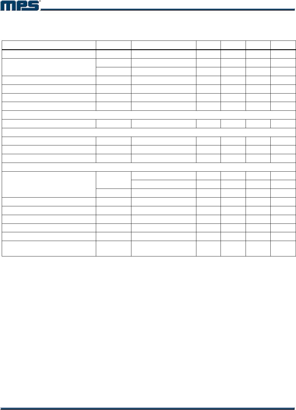
ELECTRICAL CHARACTERISTICS (continued)
V
CC
= 15V, C
GATE
= 1nF, T
J
= -40C~+125C, unless otherwise noted.
Parameter Symbol Condition Min Typ Max Units
Lower clamp voltage V
ZCSclamp_L
I
ZCS
= -2.5mA 0.2 0.5 0.7 V
V
ZCS_H
V
ZCS
rising 2.1 2.21 V
Zero current sensing threshold
V
ZCS_L
V
ZCS
falling 1.45 1.56 1.66 V
ZCS_DISABLE threshold V
ZCS_DISABLE_
140 185 230 mV
ZCS_EN threshold V
ZCS_EN
260 320 380 mV
Source current capability I
ZCS_source
-1.8 mA
Restart current after disable I
ZCS_res
55 85 µA
Re-Starter
Re-start time T
start
80 175 280 µs
Over Voltage
Dynamic OVP current I
OVP
35 40 45 µA
Hysteresis I
OVP_Hys
30 µA
Static OVP threshold V
OVP
2.15 2.25 2.35 V
Gate Driver
I
GDsource
= 20mA 2.4 3.1 V
V
OH
I
GDsource
= 200mA 3.9 5.0 V
Dropout voltage
V
OL
I
GDsink
= 200mA 0.9 1.9 V
Voltage fall time T
f
30 70 ns
Voltage rise time T
r
40 80 ns
Max. output drive voltage V
D_max
12 13.5 15.5 V
Source current capability I
Gate_source
-750 mA
Sink current capability I
Gate_sink
800 mA
UVLO saturation voltage V
Saturation
VCC = 0 to VCC
_ON
,
I
Gate_sink
= 10mA
0.3 V
NOTES:
6) The multiplier output is given by: V
cs
= K·V
MUTL
·(V
COMP
-2.5).
7) Guaranteed by design.

