MP44014 – BOUNDARY MODE PFC CONTROLLER
MP44014 Rev. 1.01 www.MonolithicPower.com 10
11/10/2015 MPS Proprietary Information. Patent Protected. Unauthorized Photocopy and Duplication Prohibited.
© 2015 MPS. All Rights Reserved.
OPERATION
The MP44014 is a boundary conduction mode
PFC controller optimized for the PFC pre-
regulator up to 300W and fully complies with
IEC1000-3-2 specification.
Output Voltage Regulation
The output voltage is sensed at FB through a
resistor divider from the output voltage to ground.
The accurate on-chip reference voltage and the
high performance error amplifier regulate the
output voltage accurately.
Over-Voltage Protection (OVP)
The MP44014 offers two stages of over-voltage
protection: dynamic over-voltage protection and
static over-voltage protection. With two-stage
protection, the circuit operates reliably.
The MP44014 achieves OVP by monitoring the
current flow through COMP.
During steady-state operation, the current flow
through the high-side feedback resistor (R9) and
the low-side feedback resistor (R10) is calculated
with Equation (1):
OFB
FB
R9 R10
VV
V
II
R9 R10
(1)
If there is an abrupt rise on the output (ΔV
O
) and
the compensation network connected between
FB and COMP takes time to achieve high power
factor (PF) due to the long RC time constant, the
voltage on FB will still be kept at the reference
value. The current through R10 remains equal to
V
FB
/R10. However, the current through R9 is
calculated with Equation (2):
'
OOFB
R9
VVV
I
R9
(2)
This current has to flow into COMP.
Simultaneously, this current is monitored inside
the chip. If the current rises to 35µA, the output
voltage of the multiplier will be forced to decrease,
and the energy delivered to the output will be
reduced. If this current continues to rise to about
40µA, the dynamic OVP can be triggered.
Consequently, the gate driver is blocked to turn
off the external power MOSFET, and the device
enters an idle state. This state is maintained until
the current falls below 10µA, the point at which
the internal starter will be re-enabled and allow
the switching to restart.
When the load is very light, the output voltage
tends to stay steadily above the nominal value. In
this condition, the error amplifier output will
saturate low. When the error amplifier output is
lower than 2.25V, static OVP will be triggered.
Consequently, the gate driver will be blocked to
turn off the external power MOSFET, and the
device will enter an idle state. Normal operation
resumes once the error amplifier output returns
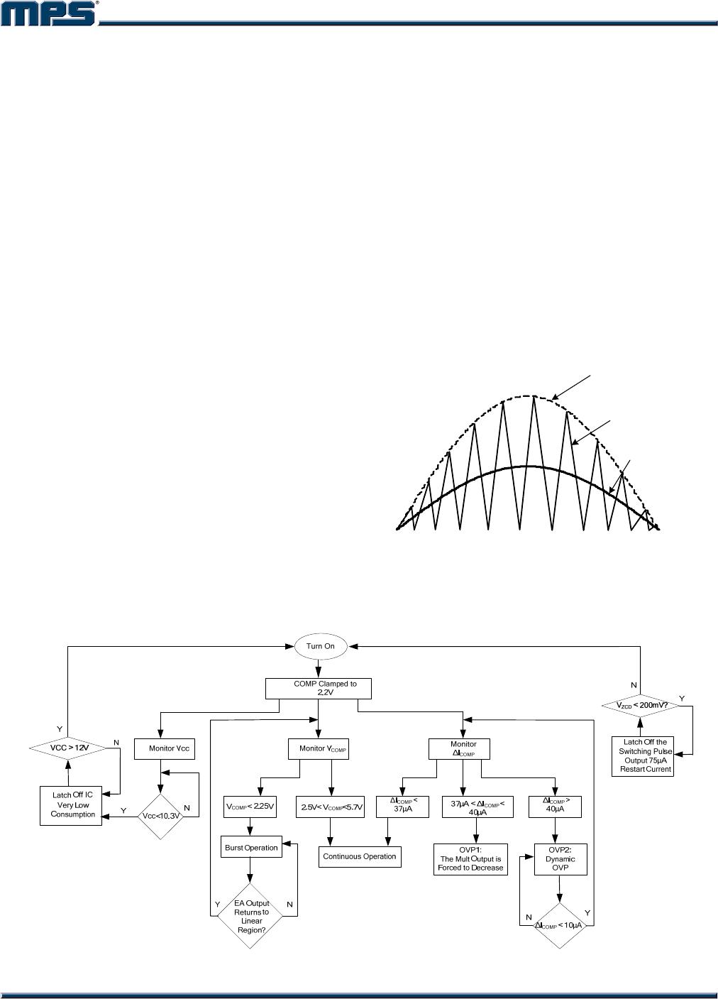
to the regulated region (see Figure 2).
Figure 2: OVP Detector Block
Disable Function
The MP44014 can be disabled by pulling the
zero-current sensing (ZCS) pin lower than
190mV. This helps to further reduce quiescent
current when the PFC pre-regulator needs to be
shut down. After releasing ZCS, it will stay at a
lower clamp voltage when there is no external
voltage from the auxiliary winding (see Figure 3).
Figure 3: ZCS Triggering and Disable Block