PROGRAMMABLE CLOCK GENERATOR 10 MARCH 3, 2017
5P49V5901 DATASHEET
I
2
C Mode Operation
The device acts as a slave device on the I
2
C bus using one of
the two I
2
C addresses (0xD0 or 0xD4) to allow multiple
devices to be used in the system. The interface accepts
byte-oriented block write and block read operations. Two
address bytes specify the register address of the byte position
of the first register to write or read. Data bytes (registers) are
accessed in sequential order from the lowest to the highest
byte (most significant bit first). Read and write block transfers
can be stopped after any complete byte transfer. During a
write operation, data will not be moved into the registers until
the STOP bit is received, at which point, all data received in
the block write will be written simultaneously.
For full electrical I
2
C compliance, it is recommended to use
external pull-up resistors for SDATA and SCLK. The internal
pull-down resistors have a size of 100k typical.
I
2
C Slave Read and Write Cycle Sequencing
MARCH 3, 2017 11 PROGRAMMABLE CLOCK GENERATOR
5P49V5901 DATASHEET
Table 6:I
2
C Bus DC Characteristics
Table 7:I
2
C Bus AC Characteristics
Symbol Parameter Conditions Min Typ Max Unit
VIH Input HIGH Level
For SEL1/SDA pin and SEL0/SCL pi
n
0.7xVDDD 5.5
2
V
VIL Input LOW Level
For SEL1/SDA pin and SEL0/SCL pi
n
GND-0.3 0.3xVDDD V
VHYS Hysteresis of Inputs 0.05xVDDD V
IIN Input Leakage Current -1 30 µA
VOL Output LOW Voltage IOL = 3 mA 0.4 V
Symbol Parameter Min Typ Max Unit
FSCLK Serial Clock Frequency (SCL) 10 400 kHz
tBUF Bus free time between STOP and START 1.3 µs
tSU:START Setup Time, START 0.6 µs
tHD:START Hold Time, START 0.6 µs
tSU:DATA Setup Time, data input (SDA) 0.1 µs
tHD:DATA Hold Time, data input (SDA) 1 0 µs
tOVD Output data valid from clock 0.9 µs
CB Capacitive Load for Each Bus Line 400 pF
tR Rise Time, data and clock (SDA, SCL) 20 + 0.1xCB 300 ns
tF Fall Time, data and clock (SDA, SCL) 20 + 0.1xCB 300 ns
tHIGH HIGH Time, clock (SCL) 0.6 µs
tLOW LOW Time, clock (SCL) 1.3 µs
tSU:STOP Setup Time, STOP 0.6 µs
Note 1: A device must internally provide a hold time of at least 300 ns for the SDA signal (referred to the VIH(MIN) of the SCL signal) to bridge the
undefined region of the falling edge of SCL.
Note 2: I2C inputs are 5V tolerant.
PROGRAMMABLE CLOCK GENERATOR 12 MARCH 3, 2017
5P49V5901 DATASHEET
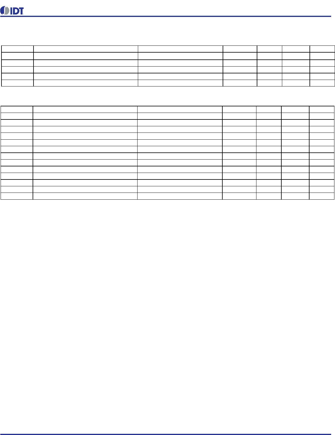
Table 8:Absolute Maximum Ratings
Stresses above the ratings listed below can cause permanent damage to the 5P49V5901. These ratings, which are standard values for IDT
commercially rated parts, are stress ratings only. Functional operation of the device at these or any other conditions above those indicated in
the operational sections of the specifications is not implied. Exposure to absolute maximum rating conditions for extended periods can affect
product reliability. Electrical parameters are guaranteed only over the recommended operating temperature range.
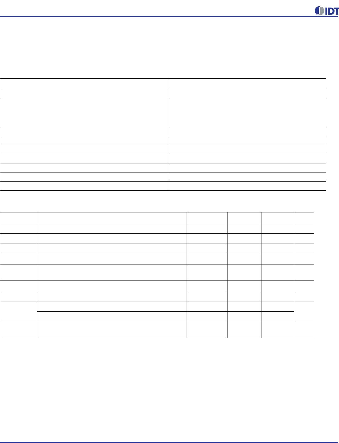
Table 9:Recommended Operation Conditions
Note: V
DDO
1, V
DDO
2, V
DDO
3, and V
DDO
4 must be powered on either before or simultaneously with V
DDD
, V
DDA
and V
DDO
0.
Item Rating
Supply Voltage, V
DDA,
V
DDD,
V
DDO
3.465V
Inputs
XIN/REF
CLKIN, CLKINB
Other inputs
0V to 1.2V voltage swing
0V to 1.2V voltage swing single-ended
-0.5V to V
DDD
Outputs, V
DDO
(LVCMOS) -0.5V to V
DDO
+ 0.5V
Outputs, I
O
(SDA) 10mA
Package Thermal Impedance,
JA
42C/W (0 mps)
Package Thermal Impedance,
JC
41.8C/W (0 mps)
Storage Temperature, T
STG
-65C to 150C
ESD Human Body Model 2000V
Junction Temperature 125°C
Symbol Parameter Min Typ Max Unit
V
DDOX
Power supply voltage for supporting 1.8V outputs
1.71 1.8 1.89 V
V
DDOX
Power supply voltage for supporting 2.5V outputs
2.375 2.5 2.625 V
V
DDOX
Power supply voltage for supporting 3.3V outputs
3.135 3.3 3.465 V
V
DDD
Power supply voltage for core logic functions
1.71 3.465 V
V
DDA
Analog power supply voltage. Use filtered analog power
supply.
1.71 3.465 V
T
A
Operating temperature, ambient
-40 +85 °C
C
LOAD_OUT
Maximum load capacitance (3.3V LVCMOS only)
15 pF
F
IN
External reference crystal
840MHz
External reference clock CLKIN, CLKINB
5350
t
PU
Power up time for all V
DD
s to reach minimum specified
voltage (power ramps must be monotonic)
0.05 5 ms

5P49V5901B045NLGI8

Mfr. #:
Manufacturer:
IDT
Description:
Clock Generators & Support Products VersaClock 5 CLK Gen 350MHz 2 Input
Lifecycle:
New from this manufacturer.
Delivery:
DHL FedEx Ups TNT EMS
Payment:
T/T Paypal Visa MoneyGram Western Union