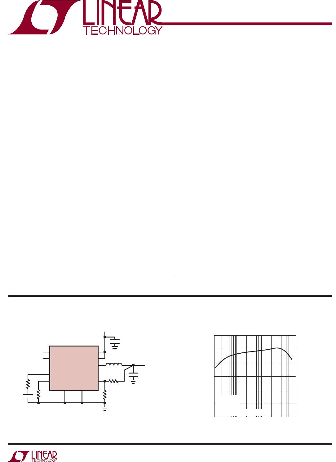
LTC3411
3
3411fb
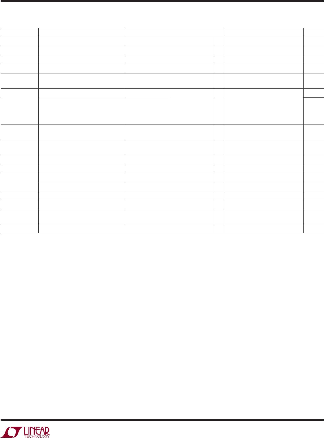
ELECTRICAL CHARACTERISTICS
The l denotes the specifi cations which apply over the full operating
temperature range, otherwise specifi cations are at T
A
= 25°C. V
IN
= 3.3V, R
T
= 324k unless otherwise specifi ed. (Note 2)
SYMBOL PARAMETER CONDITIONS MIN TYP MAX UNITS
V
IN
Operating Voltage Range 2.625 5.5 V
I
FB
Feedback Pin Input Current ±0.1 μA
V
FB
Feedback Voltage (Note 3)
l
0.784 0.8 0.816 V
ΔV
LINEREG
Reference Voltage Line Regulation V
IN
= 2.7V to 5V 0.04 0.2 %/V
ΔV
LOADREG
Output Voltage Load Regulation I
TH
= 0.36, (Note 3)
I
TH
= 0.84, (Note 3)
l
l
0.02
–0.02
0.2
–0.2
%
%
g
m(EA)
Error Amplifi er Transconductance I
TH
Pin Load = ±5μA (Note 3) 800 μS
I
S
Input DC Supply Current (Note 4)
Active Mode
Sleep Mode
Shutdown
V
FB
= 0.75V, SYNC/MODE = 3.3V
V
SYNC/MODE
= 3.3V, V
FB
= 1V
V
SHDN/RT
= 3.3V
240
62
0.1
350
100
1
μA
μA
μA
V
SHDN/RT
Shutdown Threshold High
Active Oscillator Resistor
V
IN
– 0.6
324k
V
IN
– 0.4
1M
V
Ω
f
OSC
Oscillator Frequency R
T
= 324k
(Note 7)
0.85 1 1.15
4
MHz
MHz
f
SYNC
Synchronization Frequency (Note 7) 0.4 4 MHz
I
LIM
Peak Switch Current Limit I
TH
= 1.3 1.6 2 A
R
DS(ON)
Top Switch On-Resistance (Note 6) V
IN
= 3.3V 0.11 0.15 Ω
Bottom Switch On-Resistance (Note 6) V
IN
= 3.3V 0.11 0.15 Ω
I
SW(LKG)
Switch Leakage Current V
IN
= 6V, V
ITH/RUN
= 0V, V
FB
= 0V 0.01 1 μA
V
UVLO
Undervoltage Lockout Threshold V
IN
Ramping Down 2.375 2.5 2.625 V
PGOOD Power Good Threshold V
FB
Ramping Up, SHDN/R
T
= 1V
V
FB
Ramping Down, SHDN/R
T
= 1V
6.8
–7.6
%
%
R
PGOOD
Power Good Pull-Down On-Resistance 118 200 Ω
Note 1: Stresses beyond those listed under Absolute Maximum Ratings
may cause permanent damage to the device. Exposure to any Absolute
Maximum Rating condition for extended periods may affect device
reliability and lifetime.
Note 2: The LTC3411E is guaranteed to meet specifi ed performance from
0°C to 85°C. Specifi cations over the –40°C to 85°C operating termperature
range are assured by design, characterization and correlation with
statistical process controls. The LTC3411I is guaranteed to meet specifi ed
performance over the full –40°C to 125°C operating temperature range.
Note 3: The LTC3411 is tested in a feedback loop which servos V
FB
to the
midpoint for the error amplifi er (V
ITH
= 0.6V).
Note 4: Dynamic supply current is higher due to the internal gate charge
being delivered at the switching frequency.
Note 5: T
J
is calculated from the ambient T
A
and power dissipation P
D
according to the following formula:
LTC3411DD: T
J
= T
A
+ (P
D
• 43°C/W)
LTC3411MS: T
J
= T
A
+ (P
D
• 120°C/W)
Note 6: Switch on-resistance is guaranteed by correlation to wafer level
measurements.
Note 7: 4MHz operation is guaranteed by design but not production tested
and is subject to duty cycle limitations (see Applications Information).
Note 8: This IC includes overtemperature protection that is intended
to protect the device during momentary overload conditions. Junction
temperature will exceed 125°C when overtemperature protection is active.
Continuous operation above the specifi ed maximum operating junction
temperature may impair device reliability.