NCP1582, NCP1582A, NCP1583
http://onsemi.com
3
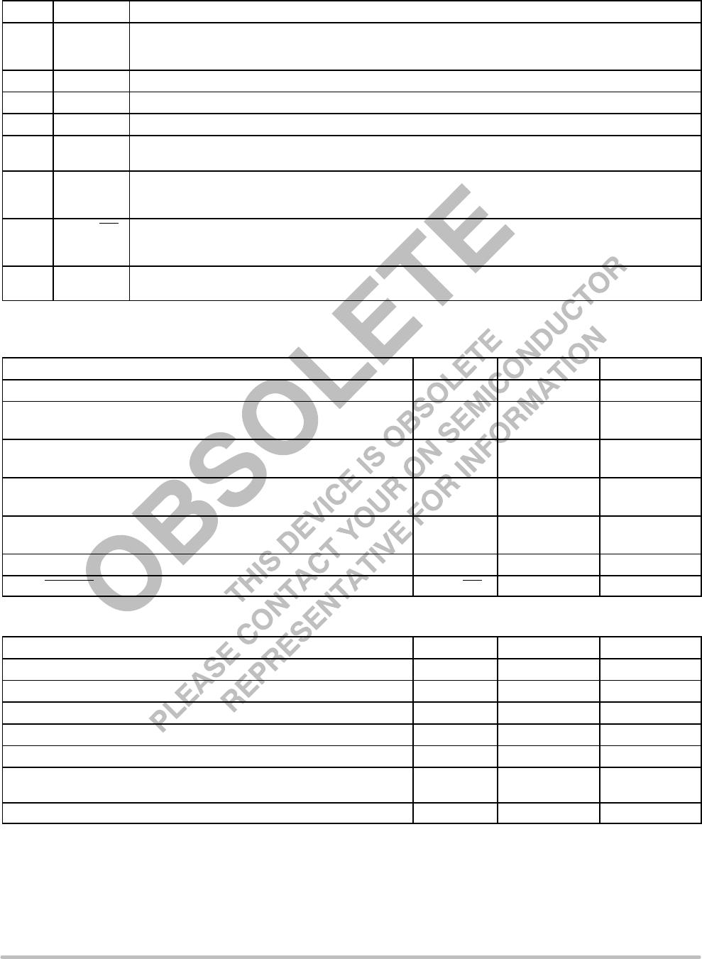
PIN FUNCTION DESCRIPTION
Pin No. Symbol Description
1 BST Supply rail for the floating top gate driver. To form a boost circuit, use an external diode to bring the
desired input voltage to this pin (cathode connected to BST pin). Connect a capacitor (C
BST
) between this pin
and the PHASE pin. Typical values for C
BST
range from 0.1 mF to 1 mF. Ensure that C
BST
is placed near the IC.
2 TG Top gate MOSFET driver pin. Connect this pin to the gate of the top N−Channel MOSFET.
3 GND IC ground reference. All control circuits are referenced to this pin.
4 BG Bottom gate MOSFET driver pin. Connect this pin to the gate of the bottom N−Channel MOSFET.
5 V
CC
Supply rail for the internal circuitry. Operating supply range is 4.5 V to 15 V. Decouple with a 1 mF
capacitor to GND. Ensure that this decoupling capacitor is placed near the IC.
6 FB This pin is the inverting input to the error amplifier. Use this pin in conjunction with the COMP pin to
compensate the voltage−control feedback loop. Connect this pin to the output resistor divider (if used) or dir-
ectly to Vout.
7 COMP/DIS Compensation Pin. This is the output of the error amplifier (EA) and the non−inverting input of the PWM com-
parator. Use this pin in conjunction with the FB pin to compensate the voltage−control feedback loop. The com-
pensation capacitor also acts as a soft−start capacitor. Pull this pin low with an open drain transistor for disable.
8 PHASE Switch node pin. This is the reference for the floating top gate driver. Connect this pin to the source of the top
MOSFET.
ABSOLUTE MAXIMUM RATINGS
Pin Name Symbol V
MAX
V
MIN
Main Supply Voltage Input V
CC
15 V −0.3 V
Bootstrap Supply Voltage Input BST 30 V wrt/GND
15 V wrt/PHASE
−0.3 V
Switching Node (Bootstrap Supply Return) PHASE 24 V −0.7 V
−5 V for < 50 ns
High−Side Driver Output (Top Gate) TG 30 V wrt/GND
15 V wrt/PHASE
−0.3 V
wrt/PHASE
Low−Side Driver Output (Bottom Gate) BG 15 V −0.3 V
−2 V for < 200 ns
Feedback FB 5.5 V −0.3 V
COMP/DISABLE COMP/DIS 5.5 V −0.3 V
MAXIMUM RATINGS
Rating Symbol Value Unit
Thermal Resistance, Junction−to−Ambient
R
q
JA
165 °C/W
Thermal Resistance, Junction−to−Case
R
q
JC
45 °C/W
Operating Junction Temperature Range T
J
−40 to 150 °C
Operating Ambient Temperature Range T
A
−40 to 85 °C
Storage Temperature Range T
stg
−55 to +150 °C
Lead Temperature Soldering (10 sec): Reflow (SMD styles only) Pb−Free
(Note 1)
260 peak °C
Moisture Sensitivity Level MSL 1 −
Stresses exceeding Maximum Ratings may damage the device. Maximum Ratings are stress ratings only. Functional operation above the
Recommended Operating Conditions is not implied. Extended exposure to stresses above the Recommended Operating Conditions may affect
device reliability.
1. 60−180 seconds minimum above 237°C.

