Micrel, Inc. MICRF002/RF022
July 2008
7
M9999-070808
Functional Diagram
Peak
Detector
AGC
Control
2nd Order
Programmable
Low-Pass Filter
5th Order
Band-Pass Filter
Synthesizer
Control
Logic
R
SC
Resettable
Counter
Reference
Oscillator
Cystal
or
Ceramic
Resonator
CAGC
ANT
SEL0
VDD
VSS
SEL1
SWEN
REFOSC
430kHz
Switched-
Capacitor
Resistor
WAKEB
CTH
DO
MICRF002
RF
Amp
IF
Amp
IF
Amp
Compa-
rator
WakeupReference and Control
UHF Downconverter
OOK Demodulator
f
RX
f
LO
f
IF
SHUT
C
AGC
C
TH
f
T
Figure 1. MICRF002 Block Diagram
Application Information and Functional
Description
Refer to Figure 1 “MICRF002 Block Diagram”. Identified in
the block diagram are the four sections of the IC: UHF
Downconverter, OOK Demodulator, Reference and
Control, and Wakeup. Also shown in the figure are two
capacitors (CTH, CAGC) and one timing component,
usually a crystal or ceramic resonator. With the exception
of a supply decoupling capacitor, and antenna impedance
matching network, these are the only external components
needed by the MICRF002 to assemble a complete UHF
receiver.
For optimal performance is highly recommended that the
MICRF002 is impedance matched to the antenna, the
matching network will add an additional two or three
components.
Four control inputs are shown in the block diagram: SEL0,
SEL1, SWEN, and SHUT. Using these logic inputs, the
user can control the operating mode and selectable
features of the IC. These inputs are CMOS compatible, and
are internally pulled-up. IF Bandpass Filter Roll-off
response of the IF Filter is 5th order, while the demodulator
data filter exhibits a 2
nd
order response.
Design Steps
The following steps are the basic design steps for using the
MICRF002 receiver:
1. Select the operating mode (sweep or fixed)
2. Select the reference oscillator
3. Select the C
TH
capacitor
4. Select the C
AGC
capacitor
5. Select the demodulator filter bandwidth
Step 1: Selecting the Operating Mode
Fixed-Mode Operation
For applications where the transmit frequency is accurately
set (that is, applications where a SAW or crystal-based
transmitter is used) the MICRF002 may be configured as a
standard superheterodyne receiver (fixed mode). In fixed-
mode operation the RF bandwidth is narrower making the
receiver less susceptible to interfering signals. Fixed mode
is selected by connecting SWEN to ground.
Sweep-Mode Operation
When used in conjunction with low-cost L-C transmitters
the MICRF002 should be configured in sweep-mode. In
sweep-mode, while the topology is still superheterodyne,
the LO (local oscillator) is swept over a range of
frequencies at rates greater than the data rate. This
technique effectively increases the RF bandwidth of the
Micrel, Inc. MICRF002/RF022
July 2008
8
M9999-070808
MICRF002, allowing the device to operate in applications
where significant transmitter-receiver frequency
misalignment may exist. The transmit frequency may vary
up to ±0.5% over initial tolerance, aging, and temperature.
In sweep-mode a band approximately 1.5% around the
nominal transmit frequency is captured. The transmitter
may drift up to ±0.5% without the need to retune the
receiver and without impacting system performance.
The swept-LO technique does not affect the IF bandwidth,
therefore noise performance is not degraded relative to
fixed-mode. The IF bandwidth is 430kHz whether the
device is operating in fixed- or sweep-mode. Due to
limitations imposed by the LO sweeping process, the upper
limit on data rate in sweep mode is approximately 5.0kbps.
Similar performance is not currently available with
crystalbased superheterodyne receivers which can operate
only with SAW- or crystal-based transmitters. In sweep-
mode, a range reduction will occur in installations where
there is a strong interferer in the swept RF band. This is
because the process indiscriminately includes all signals
within the sweep range. An MICRF002 may be used in
place of a superregenerative receiver in most applications.
Step 2: Selecting the Reference Oscillator
All timing and tuning operations on the MICRF002 are
derived from the internal Colpitts reference oscillator.
Timing and tuning is controlled through the REFOSC pin in
one of three ways:
1. Connect a ceramic resonator
2. Connect a crystal
3. Drive this pin with an external timing signal
The specific reference frequency required is related to the
system transmit frequency and to the operating mode of
the receiver as set by the SWEN pin.
Crystal or Ceramic Resonator Selection
Do not use resonators with integral capacitors since
capacitors are included in the IC, also care should be taken
to ensure low ESR capacitors are selected. Application Hint
34 and Application Hint 35 provide additional information
and recommended sources for crystals and resonators.
If operating in fixed-mode, a crystal is recommended. In
sweep-mode either a crystal or ceramic resonator may be
used. When a crystal of ceramic resonator is used the
minimum voltage is 300mV
PP
. If using an externally applied
signal it should be AC-coupled and limited to the operating
range of 0.1V
PP
to 1.5V
PP
.
Selecting Reference Oscillator Frequency f
T
(Fixed-
Mode)
As with any superheterodyne receiver, the mixing
between the internal LO (local oscillator) frequency f
LO
and
the incoming transmit frequency f
TX
ideally must equal the
IF center frequency. Equation 1 may be used to compute
the appropriate f
LO
for a given f
TX
:
(1)
±=
315
f
0.86ff
TX
TXLO
Frequencies f
TX
and f
LO
are in MHz. Note that two values of
f
LO
exist for any given f
TX
, distinguished as “high-side
mixing” and “low-side mixing”. High-side mixing results in
an image frequency above the frequency of interest and
low-side mixing results in a frequency below.
After choosing one of the two acceptable values of f
LO
, use
Equation 2 to compute the reference oscillator frequency f
T
:
(2)
64.5
f
f
LO
T
=
Frequency f
T
is in MHz. Connect a crystal of frequency f
T
to
REFOSC on the MICRF002. Four-decimal-place accuracy
on the frequency is generally adequate. The following table
identifies f
T
for some common transmit frequencies when
the MICRF002 is operated in fixed mode.
Transmit Frequency f
TX
Reference Oscillator
Frequency f
T
315MHz 4.8970MHz
390MHz 6.0630MHz
418MHz 6.4983MHz
433.92MHz 6.7458MHz
Table 2. Fixed-Mode Recommended Reference Oscillator
Values for Typical Transmit Frequencies
(high-side mixing)
Selecting REFOSC Frequency f
T
(Sweep-Mode)
Selection of the reference oscillator frequency f
T
in sweep-
mode is much simpler than in fixed mode due to the LO
sweeping process. Also, accuracy requirements of the
frequency reference component are significantly relaxed.
In sweep-mode, f
T
is given by Equation 3:
(3)
64.25
f
f
LO
T
=
In sweep-mode a reference oscillator with frequency
accurate to two-decimal-places is generally adequate. A
crystal may be used and may be necessary in some cases
if the transmit frequency is particularly imprecise.
Transmit Frequency f
TX
Reference Oscillator
Frequency f
T
315MHz 4.88MHz
390MHz 6.05MHz
418MHz 6.48MHz
433.92MHz 6.73MHz
Table 3. Sweep-Mode Recommended Reference Oscillator
Values for Typical Transmit Frequencies
Micrel, Inc. MICRF002/RF022
July 2008
9
M9999-070808
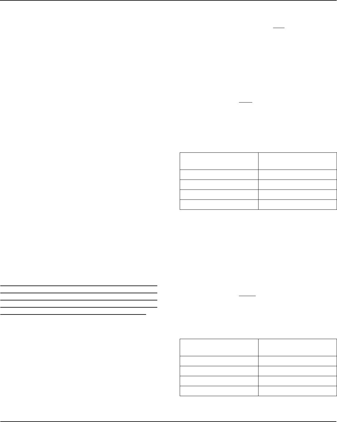
Step 3: Selecting the C
TH
Capacitor
Extraction of the dc value of the demodulated signal
for purposes of logic-level data slicing is accomplished
using the external threshold capacitor C
TH
and the on-
chip switched capacitor “resistor” R
SC
, shown in the
block diagram.
Slicing level time constant values vary somewhat with
decoder type, data pattern, and data rate, but typically
values range from 5ms to 50ms. Optimization of the
value of C
TH
is required to maximize range.
Selecting Capacitor C
TH
The first step in the process is selection of a data-slicing-
level time constant. This selection is strongly dependent on
system issues including system decode response time and
data code structure (that is, existence of data preamble,
etc.). This issue is covered in more detail in Application
Note 22.
The effective resistance of R
SC
is listed in the electrical
characteristics table as 145k at 315MHz, this value scales
linearly with frequency. Source impedance of the C
TH
pin at
other frequencies is given by Equation 4, where f
T
is in
MHz:
(4)
T
SC
f
4.8970
145kR =
τ of 5x the bit-rate is recommended. Assuming that a slicing
level time constant τ has been established, capacitor C
TH
may be computed using Equation 5:
(5)
SC
TH
R
τ
C =
A standard ±20% X7R ceramic capacitor is generally
sufficient. Refer to Application Hint 42 for C
TH
and CAGC
selection examples.
Step 4: Selecting the C
AGC
Capacitor
The signal path has AGC (automatic gain control) to
increase input dynamic range. The attack time constant of
the AGC is set externally by the value of the C
AGC
capacitor
connected to the C
AGC
pin of the device. To maximize
system range, it is important to keep the AGC control
voltage ripple low, preferably under 10mV
PP
once the
control voltage has attained its quiescent value. For this
reason capacitor values of at least 0.47µF are
recommended.
The AGC control voltage is carefully managed on-chip to
allow duty-cycle operation of the MICRF002. When the
device is placed into shutdown mode (SHUT pin pulled
high), the AGC capacitor floats to retain the voltage. When
operation is resumed, only the voltage droop due to
capacitor leakage must be replenished. A relatively low-
leakage capacitor is recommended when the devices are
used in dutycycled operation.
To further enhance duty-cycled operation, the AGC push
and pull currents are boosted for approximately 10ms
immediately after the device is taken out of shutdown. This
compensates for AGC capacitor voltage droop and reduces
the time to restore the correct AGC voltage. The current is
boosted by a factor of 45.
Selecting C
AGC
Capacitor in Continuous Mode
A C
AGC
capacitor in the range of 0.47µF to 4.7µF is typically
recommended. The value of the C
AGC
should be selected to
minimize the ripple on the AGC control voltage by using a
sufficiently large capacitor. However if the capacitor is too
large the AGC may react too slowly to incoming signals.
AGC settling time from a completely discharged (zero-volt)
state is given approximately by Equation 6:
(6) 0.441.333Ct
AGC
=
where:
C
AGC
sin in µF, and t is in seconds.
Selecting C
AGC
Capacitor in Duty-Cycle Mode
Voltage droop across the C
AGC
capacitor during shutdown
should be replenished as quickly as possible after the IC is
enabled. As mentioned above, the MICRF002 boosts the
push-pull current by a factor of 45 immediately after start-
up. This fixed time period is based on the reference
oscillator frequency f
T
. The time is 10.9ms for f
T
= 6.00MHz,
and varies inversely with f
T
. The value of C
AGC
capacitor
and the duration of the shutdown time period should be
selected such that the droop can be replenished within this
10ms period.
Polarity of the droop is unknown, meaning the AGC voltage
could droop up or down. Worst-case from a recovery
standpoint is downward droop, since the AGC pull-up
current is 1/10th magnitude of the pulldown current. The
downward droop is replenished according to the Equation
7:
(7)
t
V
C
I
AGC
=
where:
I = AGC pullup current for the initial 10ms (67.5µA)
C
AGC
= AGC capacitor value
t = droop recovery time
V = droop voltage
For example, if user desires t = 10ms and chooses a
4.7µF C
AGC
, then the allowable droop is about 144mV.
Using the same equation with 200nA worst case pin
leakage and assuming 1µA of capacitor leakage in the
same direction, the maximum allowable t (shutdown time)
is about 0.56s for droop recovery in 10ms.
The ratio of decay-to-attack time-constant is fixed at 10:1
(that is, the attack time constant is 1/10th of the decay time
constant). Generally the design value of 10:1 is adequate

MICRF002YM

Mfr. #:
Manufacturer:
Microchip Technology / Micrel
Description:
RF Receiver (Not Recommended for New Designs)300-440MHz RF Receiver With Shutdown
Lifecycle:
New from this manufacturer.
Delivery:
DHL FedEx Ups TNT EMS
Payment:
T/T Paypal Visa MoneyGram Western Union