4
IDT72205LB/72215LB/72225LB/72235LB/72245LB CMOS SyncFIFO
TM
256 x 18, 512 x 18, 1,024 x 18, 2,048 x 18 and 4,096 x 18
COMMERCIAL AND INDUSTRIAL
TEMPERATURE RANGES
MARCH 2013
RECOMMENDED DC OPERATING
CONDITIONS
Symbol Parameter Min. Typ. Max. Unit
VCC Supply Voltage 4.5 5.0 5.5 V
Commercial/Industrial
GND Supply Voltage 0 0 0 V
V
IH Input High Voltage 2.0 V
Commercial/Industrial
V
IL
(1)
Input Low Voltage 0.8 V
Commercial/Industrial
T
A Operating Temperature 0 70 °C
Commercial
T
A Operating Temperature -40 85 °C
Industrial
NOTE:
1. 1.5V undershoots are allowed for 10ns once per cycle.
Symbol Rating Commercial Unit
V
TERM Terminal Voltage –0.5 to +7.0 V
with respect to GND
T
STG Storage –55 to +125 °C
Temperature
I
OUT DC Output Current –50 to +50 mA
Symbol Parameter
(1)
Conditions Max. Unit
CIN
(2)
Input VIN = 0V 10 pF
Capacitance
C
OUT
(1,2)
Output VOUT = 0V 10 pF
Capacitance
CAPACITANCE (TA = +25°C, f = 1.0MHz)
NOTES:
1. With output deselected, (OE VIH).
2. Characterized values, not currently tested.
IDT72205LB
IDT72215LB
IDT72225LB
IDT72235LB
IDT72245LB
Commercial and Industrial
(1)
tCLK = 10, 15, 25 ns
Symbol Parameter Min. Typ. Max. Unit
I
LI
(2)
Input Leakage Current (any input) 1 1 μA
I
LO
(3)
Output Leakage Current 10 10 μA
V
OH Output Logic “1” Voltage, IOH = –2 mA 2.4 V
V
OL Output Logic “0” Voltage, IOL = 8 mA 0.4 V
I
CC1
(4,5,6)
Active Power Supply Current 60 mA
DC ELECTRICAL CHARACTERISTICS
(Commercial: VCC = 5V ± 10%, TA = 0°C to +70°C; Industrial: VCC = 5V ± 10%V, TA = -40°C to +85°C)
NOTES:
1. Industrial Temperature Range Product for the 15ns and the 25ns speed grades are available as a standard device.
2. Measurements with 0.4 VIN VCC.
3. OE VIH, 0.4 VOUT VCC.
4. Tested with outputs disabled (IOUT = 0).
5. RCLK and WCLK toggle at 20 MHZ and data inputs switch at 10 MHz.
6. For the IDT72205/72215/72225 the typical ICC1 = 1.81 + 1.12*fS + 0.02*CL*fS (in mA);
for the IDT72235/72245 the typical ICC1 = 2.85 + 1.30*fS + 0.02*CL*fS (in mA)
These equations are valid under the following conditions:
VCC = 5V, TA = 25°C, fS = WCLK frequency = RCLK frequency (in MHz, using TTL levels), data switching at fS/2, CL = capacitive load (in pF).
7. All Inputs = VCC - 0.2V or GND + 0.2V, except RCLK and WCLK, which toggle at 20 MHz.
ABSOLUTE MAXIMUM RATINGS
NOTES:
1. Stresses greater than those listed under ABSOLUTE MAXIMUM RATINGS may cause
permanent damage to the device. This is a stress rating only and functional operation
of the device at these or any other conditions above those indicated in the operational
sections of this specification is not implied. Exposure to absolute maximum rating
conditions for extended periods may affect reliability.
ICC2
(4,7)
Standby Current 5 mA
5
IDT72205LB/72215LB/72225LB/72235LB/72245LB CMOS SyncFIFO
TM
256 x 18, 512 x 18, 1,024 x 18, 2,048 x 18 and 4,096 x 18
COMMERCIAL AND INDUSTRIAL
TEMPERATURE RANGES
MARCH 2013
AC ELECTRICAL CHARACTERISTICS
(Commercial: VCC = 5V ± 10%, TA = 0°C to +70°C; Industrial: VCC = 5V ± 10%, TA = -40°C to +85°C)
Commercial Commercial & Industrial
(1)
IDT72205LB10 IDT72205LB15 IDT72205LB25
IDT72215LB10 IDT72215LB15 IDT72215LB25
IDT72225LB10 IDT72225LB15 IDT72225LB25
IDT72235LB10 IDT72235LB15 IDT72235LB25
IDT72245LB10 IDT72245LB15 IDT72245LB25
Symbol Parameter Min. Max. Min. Max. Min. Max. Unit
fS Clock Cycle Frequency 100 66.7 40 MH z
tA Data Access Time 2 6.5 2 10 2 15 ns
tCLK Clock Cycle Time 10 15 25 ns
tCLKH Clock HIGH Time 4.5 6 10 ns
tCLKL Clock LOW Time 4.5 6 10 ns
tDS Data Set-up Time 3 4 6 ns
tDH Data Hold Time 0 1 1 ns
tENS Enable Set-up Time 3 4 6 ns
tENH Enable Hold Time 0 1 1 ns
tRS Reset Pulse Width
(2)
10 15 25 ns
tRSS Reset Set-up Time 8 10 15 ns
tRSR Reset Recovery Time 8 10 15 ns
tRSF Reset to Flag and Output Time 15 20 25 ns
tOLZ Output Enable to Output in Low-Z
(3)
0—0—0—ns
tOE Output Enable to Output Valid 3 6 3 8 3 12 ns
tOHZ Output Enable to Output in High-Z
(3)
3638312ns
tWFF Write Clock to Full Flag 6.5 10 15 ns
tREF Read Clock to Empty Flag 6.5 10 15 ns
tPAF Clock to Asynchronous Programmable Almost-Full Flag 17 24 26 ns
tPAE Clock to Programmable Almost-Empty Flag 17 24 26 ns
tHF Clock to Half-Full Flag 17 24 26 ns
tXO Clock to Expansion Out 6.5 10 15 ns
tXI Expansion In Pulse Width 3 6.5 10 ns
tXIS Expansion In Set-Up Time 3.5 5 10 ns
tSKEW1 Skew time between Read Clock & Write Clock forFull Flag 5 6 10 ns
tSKEW2
(2)
Skew time between Read Clock & Write Clock for Empty Flag 5—6—10ns
Input Pulse Levels GND to 3.0V
Input Rise/Fall Times 3ns
Input Timing Reference Levels 1.5V
Output Reference Levels 1.5V
Output Load See Figure 1
AC TEST CONDITIONS
Figure 1. Output Load
* Includes jig and scope capacitances.
30pF*
1.1K
5V
680Ω
D.U.T.
2766 drw 04
NOTES:
1. Industrial temperature range product for the 15ns and the 25ns speed grades are available as a standard device. All other speed grades are available by special order.
2. Pulse widths less than minimum values are not allowed.
3. Values guaranteed by design, not currently tested.
6
IDT72205LB/72215LB/72225LB/72235LB/72245LB CMOS SyncFIFO
TM
256 x 18, 512 x 18, 1,024 x 18, 2,048 x 18 and 4,096 x 18
COMMERCIAL AND INDUSTRIAL
TEMPERATURE RANGES
MARCH 2013
SIGNAL DESCRIPTIONS:
INPUTS:
DATA IN (D0 - D17)
Data inputs for 18-bit wide data.
CONTROLS:
RESET (RS)
Reset is accomplished whenever the Reset (RS) input is taken to a LOW state.
During reset, both internal read and write pointers are set to the first location.
A reset is required after power-up before a write operation can take place. The
Full Flag (FF), Half-Full Flag (HF) and Programmable Almost-Full Flag (PAF)
will be reset to HIGH after tRSF. The Empty Flag (EF) and Programmable
Almost-Empty Flag (PAE) will be reset to LOW after tRSF. During reset, the output
register is initialized to all zeros and the offset registers are initialized to their default
values.
WRITE CLOCK (WCLK)
A write cycle is initiated on the LOW-to-HIGH transition of the Write Clock
(WCLK). Data setup and hold times must be met with respect to the LOW-to-HIGH
transition of WCLK.
The Write and Read Clocks can be asynchronous or coincident.
WRITE ENABLE (WEN)
When the WEN input is LOW and LD input is HIGH, data may be loaded into
the FIFO RAM array on the rising edge of every WCLK cycle if the device is
not full. Data is stored in the RAM array sequentially and independently of any
ongoing read operation.
When WEN is HIGH, no new data is written in the RAM array on each WCLK
cycle.
To prevent data overflow, FF will go LOW, inhibiting further write operations.
Upon the completion of a valid read cycle, FF will go HIGH allowing a write to
occur. The FF flag is updated on the rising edge of WCLK. WEN is ignored
when the FIFO is full.
READ CLOCK (RCLK)
Data can be read on the outputs on the LOW-to-HIGH transition of the Read
Clock (RCLK), when Output Enable (OE) is set LOW.
The Write and Read Clocks can be asynchronous or coincident.
READ ENABLE (REN)
When Read Enable is LOW and LD input is HIGH, data is loaded from the
RAM array into the output register on the rising edge of every RCLK cycle if
the device is not empty.
When the REN input is HIGH, the output register holds the previous data and
no new data is loaded into the output register. The data outputs Q
0-Qn maintain
the previous data value.
Every word accessed at Qn, including the first word written to an empty
FIFO, must be requested using REN. When the last word has been read from
the FIFO, the Empty Flag (EF) will go LOW, inhibiting further read operations.
REN is ignored when the FIFO is empty. Once a write is performed, EF will
go HIGH allowing a read to occur. The EF flag is updated on the rising edge
of RCLK.
OUTPUT ENABLE (OE)
When Output Enable (OE) is enabled (LOW), the parallel output buffers
receive data from the output register. When OE is disabled (HIGH), the Q output
data bus is in a high-impedance state.
LOAD (LD)
The IDT72205LB/72215LB/72225LB/72235LB/72245LB devices con-
tain two 12-bit offset registers with data on the inputs, or read on the outputs.
When the Load (LD) pin is set LOW and WEN is set LOW, data on the inputs
D0-D11 is written into the Empty Offset register on the first LOW-to-HIGH
transition of the Write Clock (WCLK). When the LD pin and (WEN) are held
LOW then data is written into the Full Offset register on the second LOW-to-HIGH
transition of (WCLK). The third transition of the write clock (WCLK) again writes
to the Empty Offset register.
However, writing all offset registers does not have to occur at one time. One
or two offset registers can be written and then by bringing the LD pin HIGH, the
FIFO is returned to normal read/write operation. When the LD pin is set LOW,
and WEN is LOW, the next offset register in sequence is written.
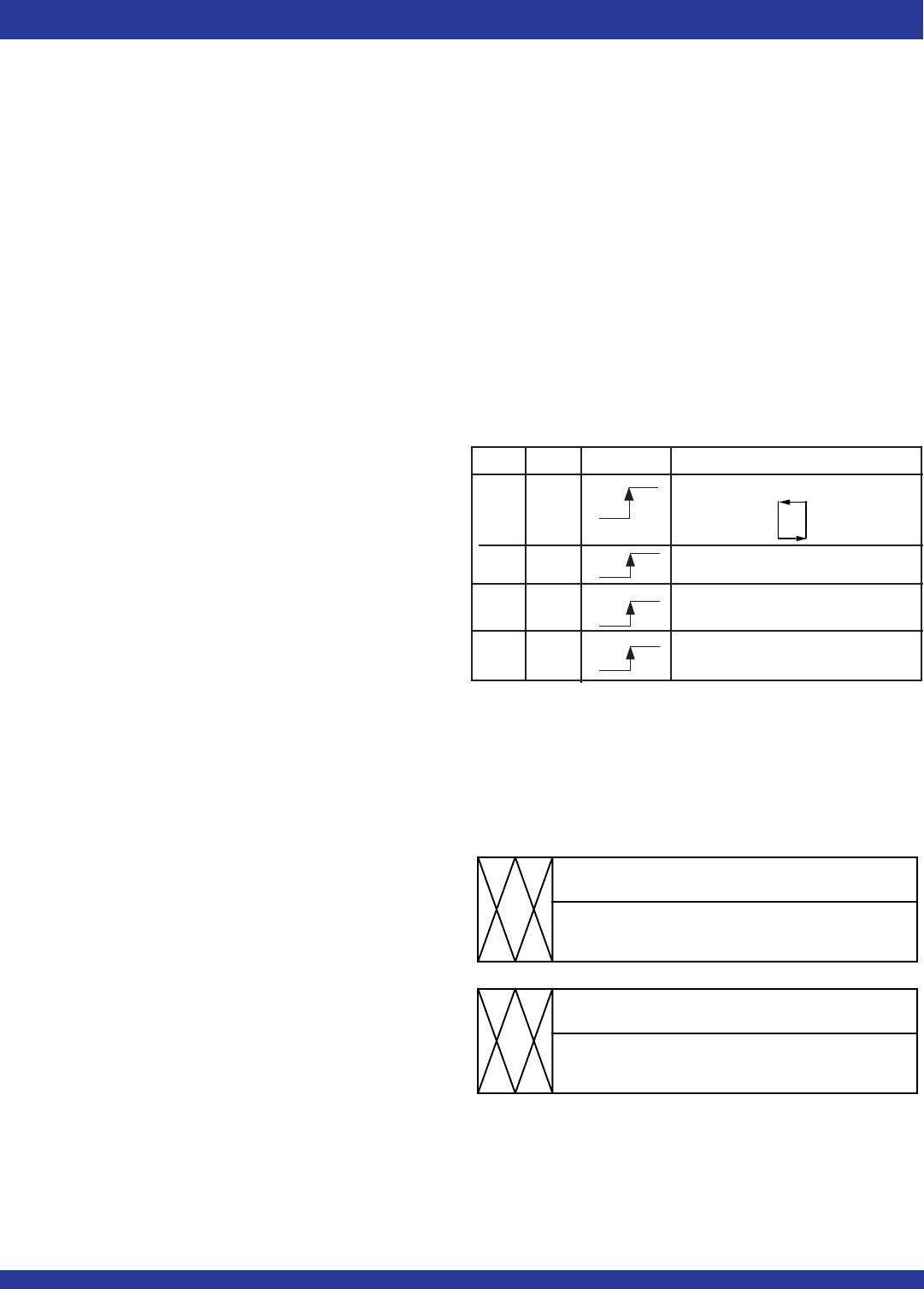
EMPTY OFFSET REGISTER
17
11
0
001FH (72205) 003FH (72215):
007FH (72225/72235/72245)
FULL OFFSET REGISTER
17
11
0
DEFAULT VALUE
DEFAULT VALUE
001FH (72205) 003FH (72215):
007FH (72225/72235/72245)
2766 drw 05
Figure 2. Write Offset Register
NOTE:
1. The same selection sequence applies to reading from the registers. REN is enabled and
read is performed on the LOW-to-HIGH transition of RCLK.
Figure 3. Offset Register Location and Default Values
NOTE:
1. Any bits of the offset register not being programmed should be set to zero.
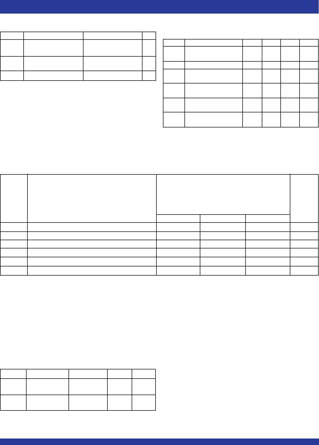
LD WEN WCLK Selection
0 0 Writing to offset registers:
Empty Offset
Full Offset
0 1 No Operation
1 0 Write Into FIFO
1 1 No Operation

72225LB15TF

Mfr. #:
Manufacturer:
IDT
Description:
FIFO 1K X 18 FIFO SYNCHRONOUS
Lifecycle:
New from this manufacturer.
Delivery:
DHL FedEx Ups TNT EMS
Payment:
T/T Paypal Visa MoneyGram Western Union