BD8153EFV
Technical Note
3/17
www.rohm.com
2009.07 - Rev.B
© 2009 ROHM Co., Ltd. All rights reserved.
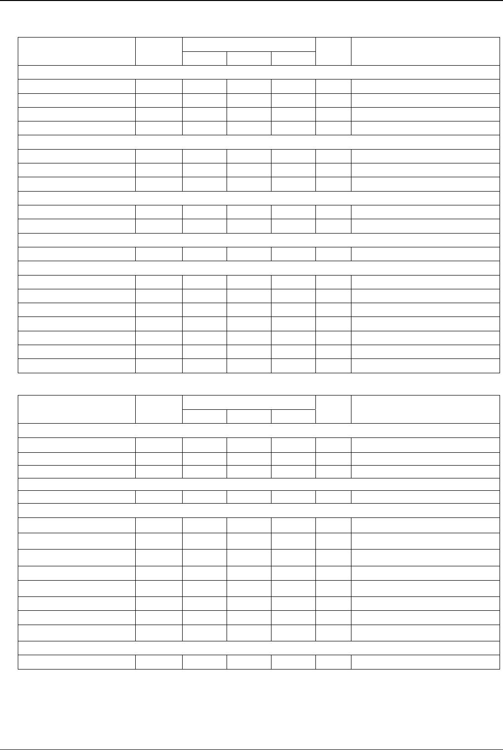
●Electrical Characteristics (Unless otherwise specified, VCC = 5 V; Vo1 = 15 V; Vo2 = 25 V; Ta = 25°C)
3.Charge pump
Parameter Symbol
Limit
Unit Conditions
Min. Typ. Max.
[Error amp]
Input bias current 2 IFB2 — 0.1 0.5 μA
Input bias current 3 IFB3 — 0.1 0.5 μA
Feedback voltage 2 VFB2 1.183 1.240 1.307 V
Feedback voltage 3 VFB3 0.15 0.2 0.25 V
[Delay start block]
Source current IDSO 3 5 7 μA VDLS = 0.5V
Sinking current IDSI 0.1
0.5
1.0 mA VDLS = 0.5V
Startup voltage VST 0.45 0.60 0.75 V
[Switch]
ON resistance N-channel RON_NC 0.5 2 4 Ω Io = 10 mA *
ON resistance P-channel RON_PC 0.5 4 8 Ω Io = -10 mA *
[Diode]
Voltage of diode Vf 600 710 800 mV Io = 10 mA
[Gate shading block]
ON resistance N-channel RON_NGS 2 10 20 Ω Io = 10 mA *
ON resistance P-channel RON_PGS 2 10 20 Ω Io = -10 mA *
Leak current N-channel ILEAK_NGS — — 10 μA
Leak current P-channel ILEAK_PGS — — 10 μA
High voltage IGH VDD × 0.7 VDD — V
Low voltage IGL — 0 VDD × 0.3 V
Input current IIG 8 16.5 30 μA IG = 3.3 V
4.Overall
Parameter Symbol
Limit
Unit Conditions
Min. Typ. Max.
[Reference block]
Reference voltage VREF 1.215 1.240 1.265 V
Drive current IREF — 23 — mA VREF = 0 V
Load regulation ∆V — 1 10 mV IREF = -1 mA
[Oscillator]
Oscillating frequency Fosc 0.94 1.1 1.265 MHz
[Oscillator]
DET 1 On threshold voltage VDON1 1.7 1.8 1.9 V
DET 1 Off threshold voltage VDOFF1 1.6 1.7 1.8 V
DET 2 On threshold voltage VDON2 1.02 1.12 1.22 V
DET 2 Off threshold voltage VDOFF2 0.90 1.00 1.10 V
DET 3 On threshold voltage VDON3 0.25 0.30 0.35 V
DET 3 Off threshold voltage VDOFF3 0.35 0.41 0.47 V
DET 4 On threshold voltage VDON4 1.02 1.12 1.22 V
DET 4 Off threshold voltage VDOFF4 0.90 1.00 1.10 V
[Device]
Average circuit current Icc 0.5 2 5 mA No switching
This product is not designed for protection against radio active rays.
* Design guarantee (No total shipment inspection is made.)

