REV. 0
Information furnished by Analog Devices is believed to be accurate and
reliable. However, no responsibility is assumed by Analog Devices for its
use, nor for any infringements of patents or other rights of third parties
which may result from its use. No license is granted by implication or
otherwise under any patent or patent rights of Analog Devices.
a
AD7894
One Technology Way, P.O. Box 9106, Norwood, MA 02062-9106, U.S.A.
Tel: 781/329-4700 World Wide Web Site: http://www.analog.com
Fax: 781/326-8703 © Analog Devices, Inc., 1998
5 V, 14-Bit Serial, 5 s
ADC in SO-8 Package
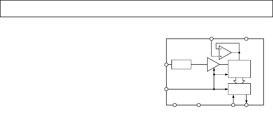
FUNCTIONAL BLOCK DIAGRAM
SIGNAL
SCALING*
TRACK/
HOLD
14-BIT
ADC
AD7894
OUTPUT
REGISTER
REF IN
V
DD
V
IN
CONVST
GND BUSY SCLK SDATA
*AD7894-10, AD7894-3
FEATURES
Fast 14-Bit ADC with 5 s Conversion Time
8-Lead SOIC Package
Single 5 V Supply Operation
High Speed, Easy-to-Use, Serial Interface
On-Chip Track/Hold Amplifier
Selection of Input Ranges
10 V for AD7894-10
2.5 V for AD7894-3
0 V to +2.5 V for AD7894-2
High Input Impedance
Low Power: 20 mW Typ
Pin Compatible Upgrade of 12-Bit AD7895
GENERAL DESCRIPTION
The AD7894 is a fast, 14-bit ADC that operates from a single
+5 V supply and is housed in a small 8-lead SOIC. The part
contains a 5 µs successive approximation A/D converter, an on-
chip track/hold amplifier, an on-chip clock and a high speed
serial interface.
Output data from the AD7894 is provided via a high speed,
serial interface port. This two-wire serial interface has a serial
clock input and a serial data output with the external serial clock
accessing the serial data from the part.
In addition to the traditional dc accuracy specifications such as
linearity, full-scale and offset errors, the AD7894 is also speci-
fied for dynamic performance parameters including harmonic
distortion and signal-to-noise ratio.
The part accepts an analog input range of ±10 V (AD7894-10),
±2.5 V (AD7894-3), 0 V to +2.5 V (AD7894-2), and operates
from a single +5 V supply consuming only 20 mW typical.
The AD7894 features a high sampling rate mode and, for low
power applications, a proprietary automatic power-down mode
where the part automatically goes into power-down once conver-
sion is complete and “wakes up” before the next conversion
cycle.
The part is available in a small outline IC (SOIC).
PRODUCT HIGHLIGHTS
1. Fast, 14-Bit ADC in 8-Lead Package
The AD7894 contains a 5␣ µs ADC, a track/hold amplifier,
control logic and a high speed serial interface, all in an 8-lead
package. This offers considerable space saving over alterna-
tive solutions.
2. Low Power, Single Supply Operation
The AD7894 operates from a single +5 V supply and con-
sumes only 20 mW. The automatic power-down mode,
where the part goes into power-down once conversion is
complete and “wakes up” before the next conversion cycle,
makes the AD7894 ideal for battery powered or portable
applications.
3. High Speed Serial Interface
The part provides high speed serial data and serial clock lines
allowing for an easy, two-wire serial interface arrangement.
AD7894* PRODUCT PAGE QUICK LINKS
Last Content Update: 02/23/2017
COMPARABLE PARTS
View a parametric search of comparable parts.
DOCUMENTATION
Data Sheet
AD7894: 5V, 14-Bit Serial, 5 us ADC in S0-8 Package Data
Sheet
Product Highlight
8- to 18-Bit SAR ADCs ... From the Leader in High
Performance Analog
TOOLS AND SIMULATIONS
AD7894 IBIS Model
REFERENCE MATERIALS
Technical Articles
MS-2210: Designing Power Supplies for High Speed ADC
DESIGN RESOURCES
AD7894 Material Declaration
PCN-PDN Information
Quality And Reliability
Symbols and Footprints
DISCUSSIONS
View all AD7894 EngineerZone Discussions.
SAMPLE AND BUY
Visit the product page to see pricing options.
TECHNICAL SUPPORT
Submit a technical question or find your regional support
number.
DOCUMENT FEEDBACK
Submit feedback for this data sheet.
This page is dynamically generated by Analog Devices, Inc., and inserted into this data sheet. A dynamic change to the content on this page will not
trigger a change to either the revision number or the content of the product data sheet. This dynamic page may be frequently modified.
–2–
REV. 0
AD7894–SPECIFICATIONS
(V
DD
= +5 V 5%, GND = 0 V, REF IN = +2.5 V. All specifications T
MIN
to T
MAX
unless
otherwise noted.)
Parameter A Versions
l
B Versions
1
Units Test Conditions/Comments
DYNAMIC PERFORMANCE
2
Signal to (Noise + Distortion) Ratio
3
@ +25°C 78 78 dB min f
IN
= 70 kHz Sine Wave, f
SAMPLE
= 160 kHz
T
MIN
to T
MAX
77 77 dB min See Figure 14
Total Harmonic Distortion (THD)
3
–86 –86 dB max f
IN
= 10 kHz Sine Wave, f
SAMPLE
= 160 kHz,
Typically –87 dB. See Figure 15
Peak Harmonic or Spurious Noise
3
–92 –92 dB typ f
IN
= 10 kHz Sine Wave, f
SAMPLE
= 160 kHz
Intermodulation Distortion (IMD)
3
fa = 9 kHz, fb = 9.5 kHz, f
SAMPLE
= 160 kHz
2nd Order Terms –92 –92 dB typ
3rd Order Terms –92 –92 dB typ
DC ACCURACY
Resolution 14 14 Bits
Minimum Resolution for Which
No Missing Codes Are Guaranteed 14 14 Bits
Relative Accuracy
3
±2 ±1.5 LSB max
Differential Nonlinearity
3
–1 to +1.5 –1 to +1.5 LSB max
AD7894-2
Positive Gain Error
3
±12 ±10 LSB max
Unipolar Offset Error ±8 ±6 LSB max
AD7894-10, AD7894-3 Only
Positive Gain Error
3
±8 ±6 LSB max
Negative Gain Error
3
±8 ±6 LSB max
Bipolar Zero Error ±10 ±8 LSB max
ANALOG INPUT
AD7894-10
Input Voltage Range ±10 ±10 V
Input Current 2 2 mA max See Analog Input Section
AD7894-3
Input Voltage Range ±2.5 ±2.5 V
Input Current 1.5 1.5 mA max See Analog Input Section
AD7894-2
Input Voltage Range 0 to +2.5 0 to +2.5 V
Input Current 500 500 nA max
REFERENCE INPUT
REF IN Input Voltage Range 2.375/2.625 2.375/2.625 V min/V max 2.5 V ± 5%
Input Current 1 1 µA max
Input Capacitance
4
10 10 pF max
LOGIC INPUTS
Input High Voltage, V
INH
2.4 2.4 V min V
DD
= 5 V ± 5%
Input Low Voltage, V
INL
0.8 0.8 V max V
DD
= 5 V ± 5%
Input Current, I
IN
±10 ±10 µA max V
IN
= 0 V to V
DD
Input Capacitance, C
IN
4
10 10 pF max
LOGIC OUTPUTS
Output High Voltage, V
OH
4.0 4.0 V min I
SOURCE
= 400 µA
Output Low Voltage, V
OL
0.4 0.4 V max I
SINK
= 1.6 mA
Output Coding
AD7894-10, AD7894-3 Twos Complement
AD7894-2 Straight (Natural) Binary
CONVERSION RATE
Conversion Time
Mode 1 Operation 5 5 µs max
Mode 2 Operation
5
10 10 µs max
Track/Hold Acquisition Time
3
0.35 0.35 µs max
SAMPLE AND HOLD
–3 dB Small Signal Bandwidth 7.5 7.5 MHz typ
Aperture Jitter 50 50 ps typ

AD7894BRZ-10

Mfr. #:
Manufacturer:
Analog Devices Inc.
Description:
Analog to Digital Converters - ADC Bipolar Input 5V 14B Serial 4.5uS
Lifecycle:
New from this manufacturer.
Delivery:
DHL FedEx Ups TNT EMS
Payment:
T/T Paypal Visa MoneyGram Western Union